
Holoscope: Digital Virtual Object Projector

a virtual object and projector technology, applied in the field of digital virtual object projectors, can solve the problems of low resolution of images, monochromatic, simple graphics with slow refresh rate, and inability to view from multiple angles, and achieve the effect of increasing human interactivity

Inactive Publication Date: 2015-03-05
SIBLEY THOMAS S
View PDF6 Cites 15 Cited by
  • Summary
  • Abstract
  • Description
  • Claims
  • Application Information

AI Technical Summary

Benefits of technology

The present invention provides a 3D viewing platform for medical imaging technologies that can display several layered medical imaging platforms to increase diagnostic proficiency. It also provides an immersive virtual reality environment with a matrix of modular devices of varying sizes and allows for tele-presence interface to reproduce the partial or complete human form in real time and increase the human interactivity of tele-presence and tele-conferencing. Additionally, it provides a virtual interactive teaching / instructional tool for children and adults that can enhance remote collaborations between teacher and student.

Problems solved by technology

Current auto-stereoscopic, 3D display technology exists that can generate a virtual image without an optical substrate, however images remain low resolution, monochromatic, simple graphics with slow refresh rates.
The drawback of such systems is that they are not viewable from multiple angles and do not produce an independent virtual object or spatially augmented reality.
Further, they often require expensive hardware configurations to function and depend upon rotational elements, which are subject to mechanical failure, reduced scalability, and limit the resolution of auto-stereoscopic content.
This system is limited by it's a rotatable view-angle restrictive filter and a display system, which does not permit high resolution or complex auto-stereoscopic images to be used due to its image source.
It employs an electro-optic directional (e.g. holographic) filter which is a rotating element, subject to mechanical failure and limited scalability.
This type of an electro-optic directional filter does not permit a high resolution, motion graphic to be displayed at the current time.
However, designed for kiosks and vending machines, it is accordingly encased within an enclosure and as such is not viewable from multiple sides.
This system is limited by its use of an optical substrate, which is in this case a transparent smooth foil.

Method used


Image

  • Holoscope: Digital Virtual Object Projector
  • Holoscope: Digital Virtual Object Projector

Examples


Embodiment Construction

1. Definitions

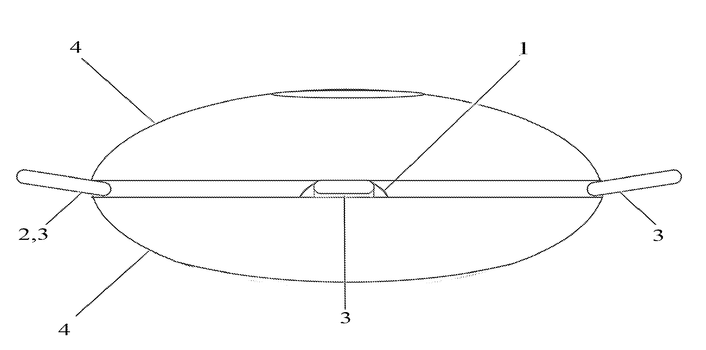
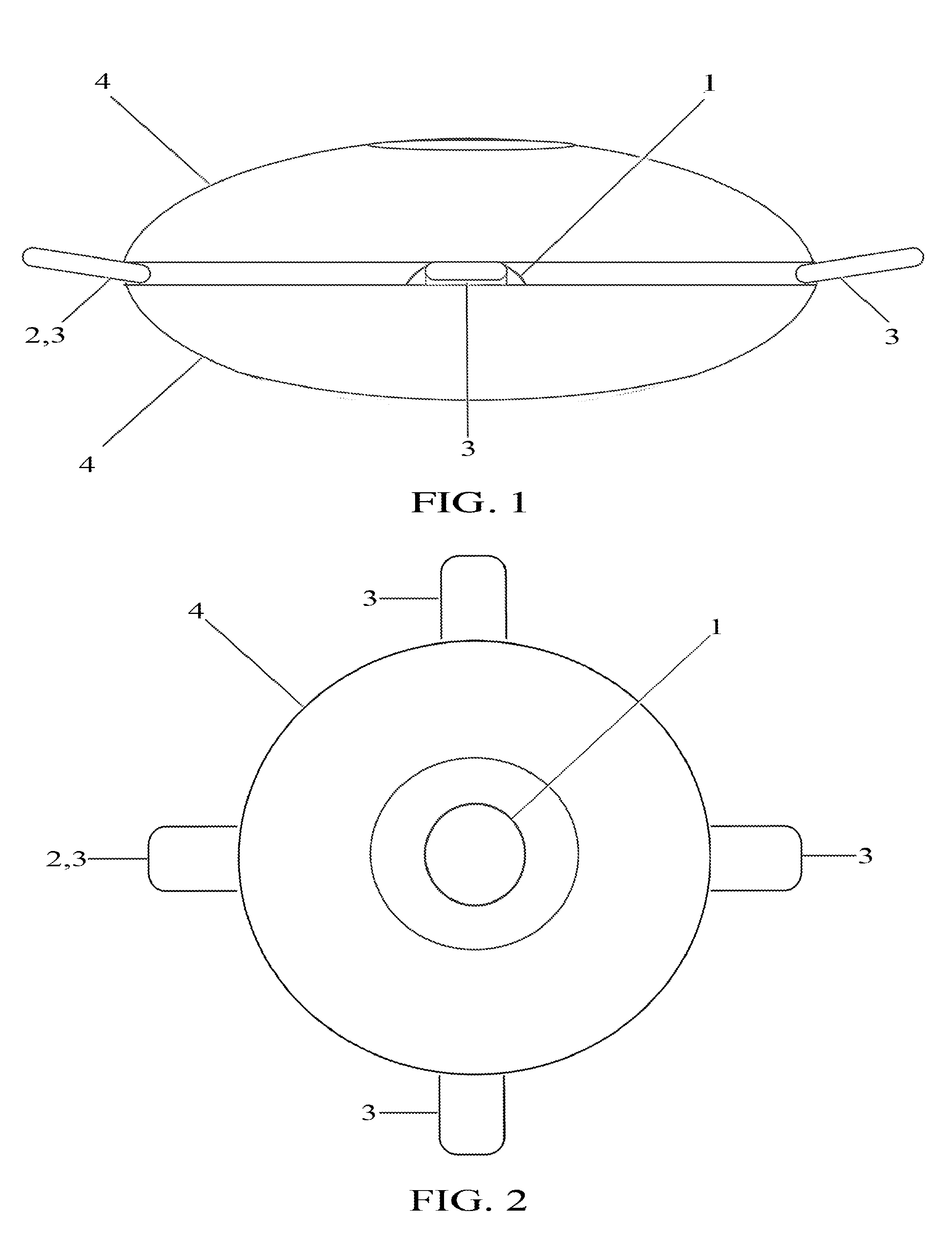
[0029]Target object as used herein shall mean a real object that acts as a 3D screen upon which the micro-projectors project visual information.

[0030]Micro-projectors as used herein shall mean small projectors which are of an appropriate focal length to project on the target object and are small enough to work within the parabolic minor assembly.

[0031]The parabolic mirror assembly as used herein shall mean an assembly of two parabolic minors facing each other and separated at an optimal distance with apertures at the top and bottom to generate interference patterns and allow projections from beneath as required.

[0032]Object and form as used herein shall be interchangeable terms.

[0033]Holoscope and digital virtual object projector as used herein shall be interchangeable terms.

2. Best Mode of Invention

[0034]FIG. 1 shows a side sectional view of the best mode contemplated by the inventor of the digital virtual object projector according to the concept of the present inven...


PUM


Abstract

Disclosed is a digital virtual object projector capable of projecting an auto-stereoscopic, 3D, high definition, virtual object or motion graphic upon three-dimensional space. Producing a collective, interactive, virtual platform viewable from multiple angles, the Holoscope is adaptable to a variety of digital imaging applications and can support traditional imaging formats. The Holoscope can project an auto-stereoscopic, 3D object at an improved resolution, frame rate, size, and cost than was heretofore possible. The Holoscope offers a new form of auto-stereoscopic display and spatially augmented, virtual environment.

Description

BACKGROUND OF THE INVENTION[0001]1. Field of the Invention[0002]The present invention is a digital virtual object projector, which projects an auto-stereoscopic, 3D, high definition, virtual object or motion graphic onto 3D space without the need of a headset, optical substrate, or enclosure. It uses a target object, one or several micro-projectors, a parabolic minor assembly, and specifically formatted visual information to produce a virtual, 3D display and spatially augmented reality.[0003]2. Description of the Prior Art[0004]Current versions of auto-stereoscopic, 3D, holographic or virtual object displays and projection systems often depend upon optical substrates such as emulsive films, liquid crystal displays, or other semi-transparent screens and materials to display auto-stereoscopic, 3D objects and forms. Current auto-stereoscopic, 3D display technology exists that can generate a virtual image without an optical substrate, however images remain low resolution, monochromatic,...

Claims


Application Information

Patent Timeline
IPC IPC(8): G02B27/22H04N13/04G03H1/00H04N13/00
CPCG02B27/225H04N13/0029G03H2001/0088G03H1/0005H04N13/0402H04N13/302H04N13/388G02B30/56G02B5/09G02B26/0816G02B1/002G02B30/50
Inventor SIBLEY, THOMAS S.
Owner SIBLEY THOMAS S
Learn More