Radar detection

a radar and detection technology, applied in the field of telecommunications, can solve problems such as interference between devices in wireless communication networks, and interference with the reception of signals at the second network devi

Inactive Publication Date: 2015-03-05
QUALCOMM INC
View PDF26 Cites 46 Cited by
  • Summary
  • Abstract
  • Description
  • Claims
  • Application Information

AI Technical Summary

Problems solved by technology

Communication between devices in a wireless communication network may be subject to interference.
For a communication from a first network device to a second network device, emissions of Radio Frequency (RF) energy by a nearby device may interfere with reception of signals at the second network device.
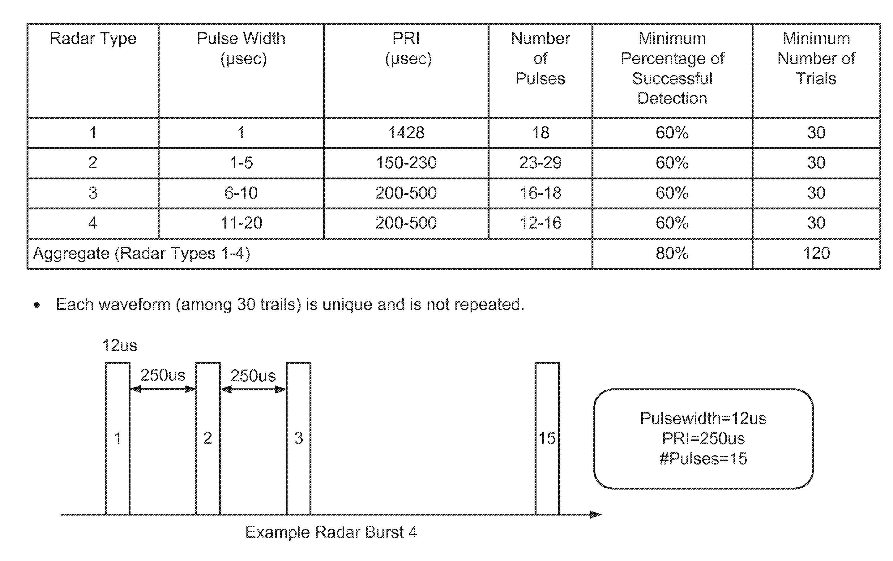
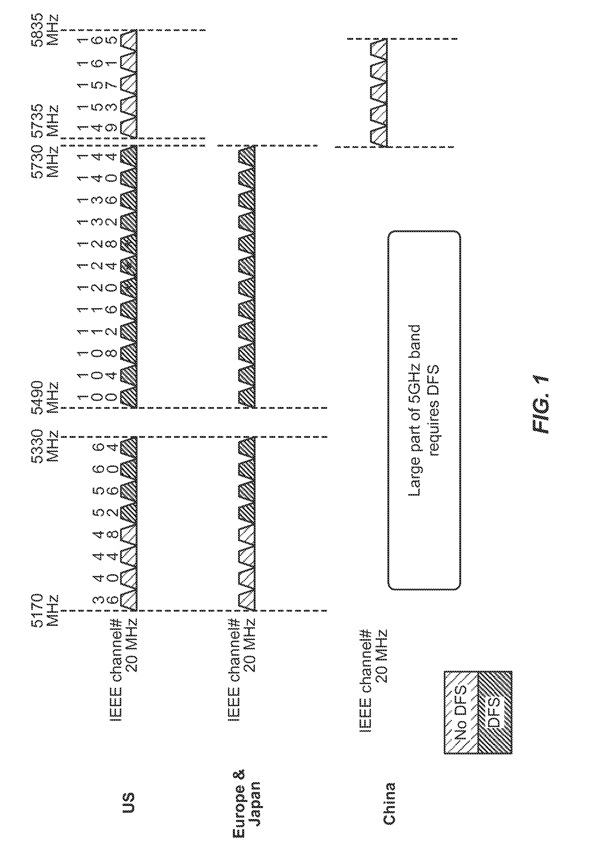
For example, some wireless communication bands (e.g., a 5 GHz band or other bands) are subject to interference from radar systems operating within those bands.
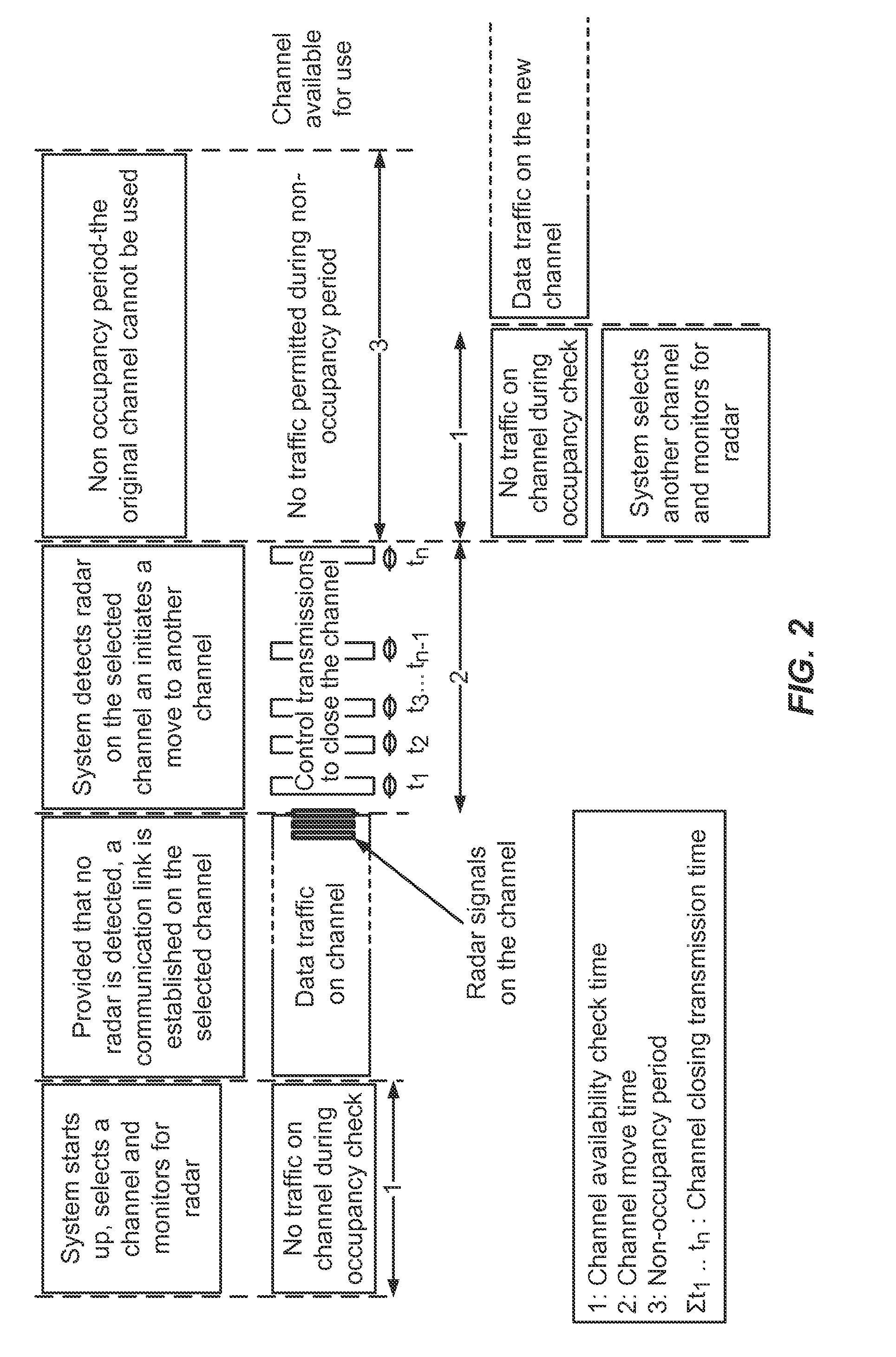
In practice, radar detection by a device may be hampered when the device is communicating with another device.
For example, radar detection might not be possible when the device is transmitting.
Thus, for technologies such as LTE time division duplexing (TDD) that employ planned transmit and receive times (e.g., time slots) on the same frequency channel, the periods of time available for radar detection may be significantly limited (e.g., limited to those times when a device is not transmitting).
For example, if the traffic duty cycle is relatively high (i.e., a high transmit to receive ratio), radar detection may be challenging due to the limited amount of time available to detect radar.
Moreover, radar detection may be unreliable even during a receive mode (e.g., in cases where a device is simultaneously receiving data and attempting to detect radar).

Method used


Image

  • Radar detection
  • Radar detection
  • Radar detection

Examples


Embodiment Construction

[0035]The disclosure relates in some aspects to techniques that provide more reliable radar detection. In this regard, a detection algorithm may generally incorporate two phases: 1) a pre-detection phase and 2) a final detection phase.

[0036]In some aspects, the pre-detection phase is a coarse detection phase that is used to trigger a finer final detection phase. Typically, the pre-detection phase makes a decision based on fewer samples (e.g., 10 samples) than the final detection phase. In this way, an initial detection of a radar signal may be made without using significant resources and may be made relatively quickly. Thus, initial detection may be invoked relatively frequently without significantly affecting system performance. However, the initial phase does not detect radar with the same level of accuracy as the final detection phase.

[0037]The final detection phase (e.g., a fine detection phase) is invoked if the pre-detection phase indicates the presence of a potential radar si...


PUM


Abstract

Systems and methods for radar detection in a communication environment are disclosed. The radar detection may comprise, for example: receiving a first signal; identifying the first signal as a potential radar signal; limiting transmission by an apparatus as a result of the identification; receiving a second signal while the transmission by the apparatus is limited; and determining whether at least one of the first signal, the second signal, or a combination thereof is a radar signal.

Description

CROSS-REFERENCE TO RELATED APPLICATIONS[0001]The present Application for Patent claims the benefit of U.S. Provisional Application No. 61 / 873,537, entitled “RADAR DETECTION,” filed Sep. 4, 2013, assigned to the assignee hereof, and expressly incorporated herein by reference in its entirety.INTRODUCTION[0002]Aspects of this disclosure relate generally to telecommunications, and more particularly to radar detection and the like.[0003]A wireless communication network may be deployed to provide various types of services (e.g., voice, data, multimedia services, etc.) to users within a coverage area of the network. In some implementations, one or more access points (e.g., corresponding to different cells) provide wireless connectivity for access terminals (e.g., cell phones) that are operating within the coverage of the access point(s). In some implementations, peer devices provide wireless connectively for communicating with one another.[0004]Communication between devices in a wireless c...

Claims


Application Information

Patent Timeline
Patent Type & Authority Applications(United States)
IPC IPC(8): H04L5/00H04W72/04
CPCH04W72/0446H04L5/0062G01S7/021H04K3/224H04K3/226H04K3/822H04K2203/16H04K2203/18H04W16/14H04L27/0006H04L5/0048H04B7/0413
Inventor SADEK, AHMED KAMELYAVUZ, MEHMET
Owner QUALCOMM INC
Why Eureka
Try Eureka