Radar, radio frequency sensor, and radar detection method

a radio frequency sensor and radar technology, applied in the field of radars, can solve the problems of significant compatibility between cost reduction and high detection performance, and achieve the effect of improving detection accuracy and reducing uncertainty in target identification

Inactive Publication Date: 2008-05-01
HITACHI LTD
View PDF28 Cites 45 Cited by
  • Summary
  • Abstract
  • Description
  • Claims
  • Application Information

AI Technical Summary

Benefits of technology

[0015]According to the present invention, it is possible to achieve a radar and a radio frequency sensor which can reduce uncertainty in target identification and improve the accuracy of detection.

Problems solved by technology

Further, the millimeter wave automotive radars operate in environments where moving objects such as vehicles are present among an extremely large number of static objects.
Conventionally, compatibility between cost reduction and high detection performance has been a significant problem.

Method used


Image

  • Radar, radio frequency sensor, and radar detection method
  • Radar, radio frequency sensor, and radar detection method
  • Radar, radio frequency sensor, and radar detection method

Examples


first embodiment

[0038]Referring to FIGS. 1 to 8, a vehicle mounted radar will now be described according to a first embodiment of the present invention.

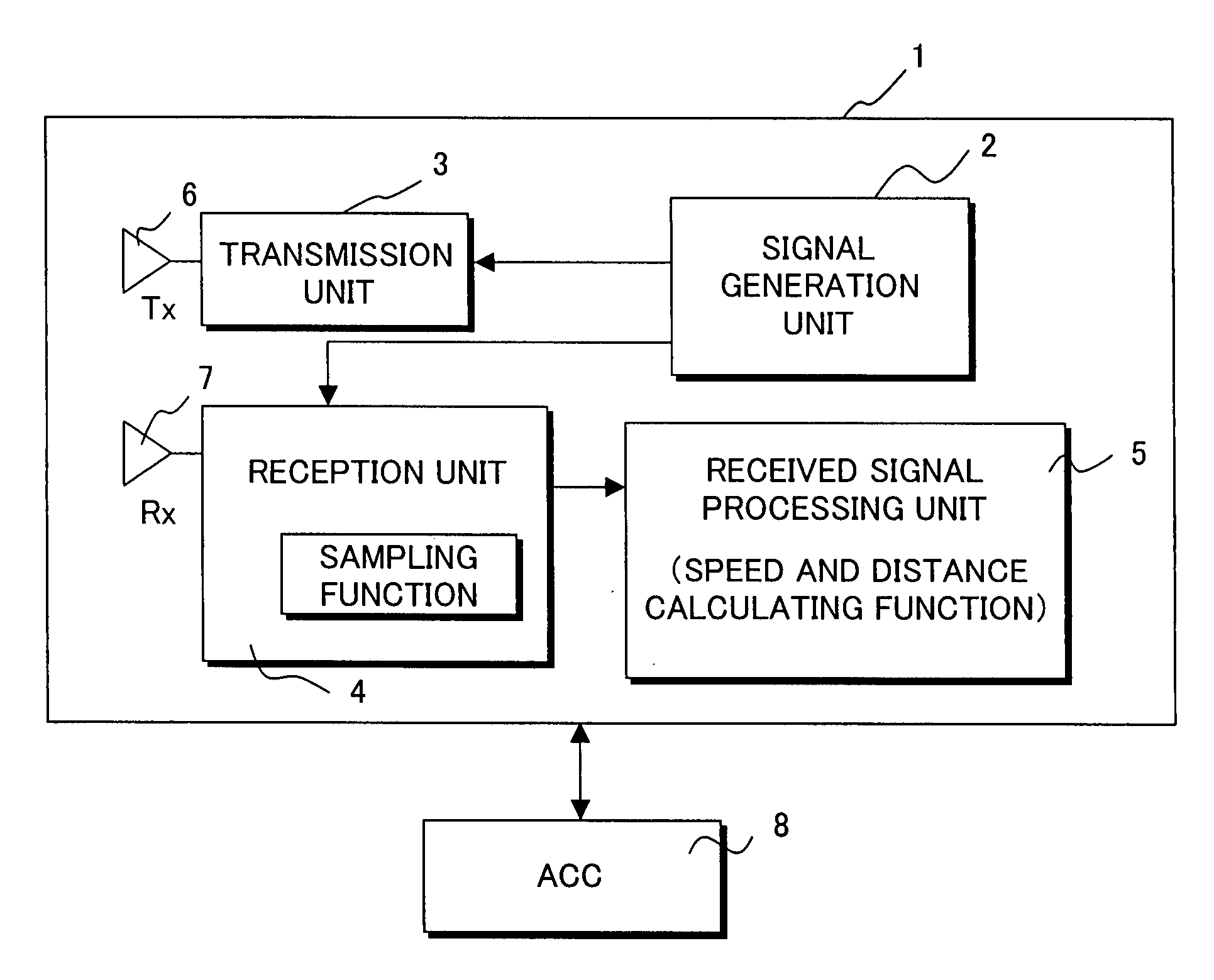
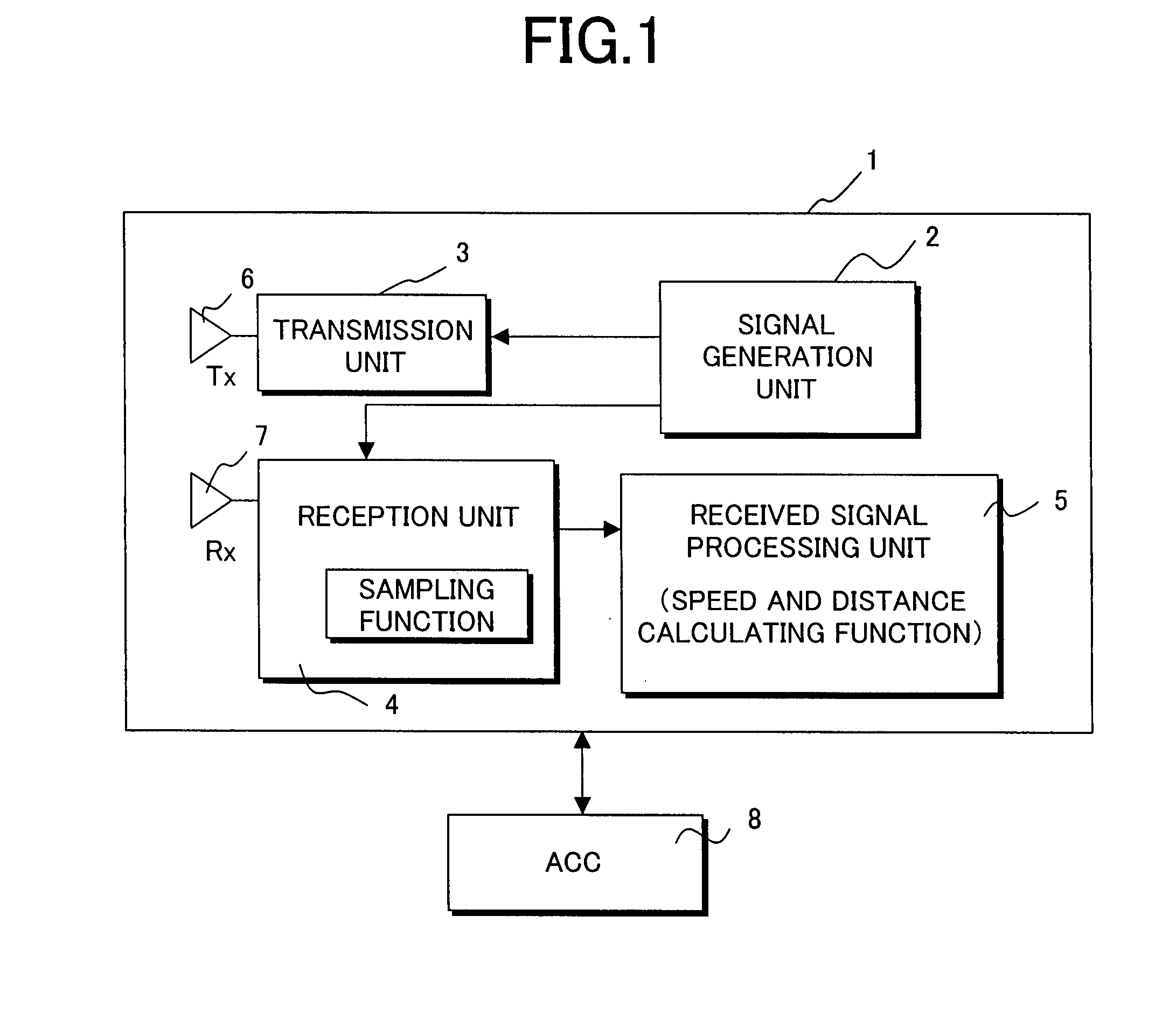
[0039]FIG. 1 is a functional block diagram for explaining the overall configuration of the vehicle mounted radar according to the first embodiment of the present invention. A vehicle mounted radar 1 includes a signal generation unit 2, a transmission unit 3, a reception unit 4, a received signal processing unit 5, a transmission antenna 6, and a reception antenna 7. A transmitted millimeter-wave signal Tx generated through the signal generation unit 2 and the transmission unit 3 is transmitted from the transmission antenna 6, a signal Rx which is the transmitted signal having been scattered on a target to be detected is received by the reception unit 4 through the reception antenna 7, and the distance and speed of the target are detected by the received signal processing unit 5. Reference numeral 8 denotes a higher level system of a vehicle.

[0040]Th...

second embodiment

[0095]In the first embodiment, a transmitted signal alternately stays on the two frequency sweep straight lines. A transmitted signal does not always have to stay on a straight line and may be periodically located alternately along positions substantially corresponding to two frequency sweep straight lines.

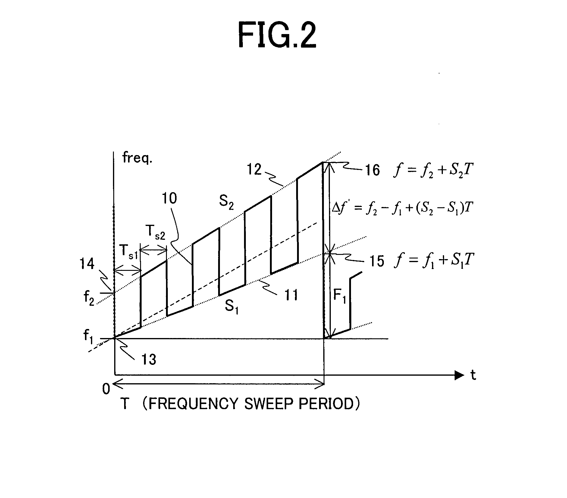
[0096]FIG. 9 shows a second embodiment of the frequency modulation pattern of a transmitted signal according to the present invention. As in FIG. 2, FIG. 9 illustrates the frequency modulation waveform of the transmitted signal as a time function.

[0097]In this example, the frequency of the transmitted signal is alternately fixed at predetermined fixed values (e.g., the value of the starting point or an intermediate value) on a frequency sweep straight line 11 extended from a first initial value f1 with a slope S1 relative to the time axis and a frequency sweep straight line 12 extended from a second initial value f2 with a second slope S2, which is different from the slope S1, rel...

third embodiment

[0103]FIG. 10 shows a third embodiment of the frequency modulation pattern of a transmitted signal according to the present invention. In this frequency modulation pattern, a frequency sweep straight line 63 with a third slope S3 is provided in addition to two frequency sweep straight lines 11 and 12 having different slopes. Sweeping is performed while switching the frequency sweep straight lines, so that three frequency equations and two phase equations can be obtained for a target, five independent equations can be provided for two unknowns (v,R) of the target with three degrees of redundancy. The increased degrees of redundancy can improve the accuracy of detection that is described in the first embodiment and can further enhance the effect of removing or reducing the possibility of erroneous detection and the possibility of undetected targets, thereby improving the performance of a radio frequency sensor.

[0104]A speed v and a distance R of a target 20 are determined as an inters...


PUM


Abstract

In a sensor and a radar for measuring the distance and the moving speed of a target by radiating a radio frequency, particularly a millimeter wave, compatibility between cost reduction and high detection performance has been conventionally a significant problem. In the present invention, the frequency of a transmitted signal changes during a fixed time while performing digitally-frequency-modulation on frequency sweeping straight lines extending, with different slopes relative to the time axis, from plural slightly different initial values serving as starting points, the signal is transmitted after being modulated so as to periodically repeat the sweep time serving as a unit, signal components corresponding to the respective sweeping slopes are digitally sampled, in synchronization with the transmitted modulation signal, from a received signal which is reflected and returned from a target, and the received signal is analyzed.

Description

CLAIM OF PRIORITY[0001]The present invention claims priority from Japanese application JP 2006-295453 filed on Oct. 31, 2006, the content of which is hereby incorporated by reference into this application.FIELD OF THE INVENTION[0002]The present invention relates to radars for measuring the distance and the moving speed of a target, sensors, and radar detection methods, and particularly relates to multi-ramp digitally-frequency-modulated radars with initial frequency offsets which are suitable for vehicle mounted radars.BACKGROUND OF THE INVENTION[0003]In order to satisfy performance required of vehicle mounted radars with low cost, various radar modulation schemes have been used. As examples of such radar modulation schemes, a frequency-modulated continuous wave (FMCW) technique, a two-frequency CW technique, and so on are disclosed in Reference 2, RCR TR-26, “Automotive Radar Research and Development Report” edited by Research & Development Center for Radio System, July 1993. The a...

Claims


Application Information

Patent Timeline
Patent Type & Authority Applications(United States)
IPC IPC(8): G01S13/34G01S13/931
CPCG01S7/35G01S13/34G01S13/931G01S13/584G01S13/347G01S7/023G01S13/343G01S7/354G01S7/0232
Inventor KONDOH, HIROSHI
Owner HITACHI LTD
Why Eureka
Try Eureka