Drive unit for a vehicle, and operating method therefor

a technology for driving units and vehicles, applied in the direction of rotary clutches, fluid couplings, gearings, etc., to achieve the effect of improving the safety and reliability of operation, and reducing the cost of operation

Inactive Publication Date: 2015-03-05
ZF FRIEDRICHSHAFEN AG
View PDF11 Cites 15 Cited by
  • Summary
  • Abstract
  • Description
  • Claims
  • Application Information

AI Technical Summary

Benefits of technology

[0013]The invention is based on the finding that a vehicle transmission in which an input clutch or an electric machine is used as a power-shift means or as a start-up means, as is common with double clutch transmissions and hybrid transmissions, can be supplemented with an additional hydrodynamic start-up element. Such a hydrodynamic start-up element, which acts on a transmission path having a start-up gear, can decouple the aforementioned power-shift clutch or the electric machine from the function of a start-up element. The power-shift clutch or the electric machine can therefore be used during vehicle operation in a more flexible manner and can be protected against increased wear.
[0056]This arrangement also makes it possible to implement start-up without delay, proceeding from a generator mode, and permits a creep mode to be implemented simultaneously with a generator mode. It is also possible to start the internal combustion engine while retaining the tractive force with slip decoupling from the transmission. A corresponding method therefor is known per se from the aforementioned document DE 10 2011 089 467 A1, which was not previously published.

Problems solved by technology

A further problem is that of providing a method for operating such a drive device.

Method used


Image

  • Drive unit for a vehicle, and operating method therefor
  • Drive unit for a vehicle, and operating method therefor
  • Drive unit for a vehicle, and operating method therefor

Examples


Embodiment Construction

[0075]For simplicity, components that are the same or are functionally equivalent are labeled with the same reference characters.

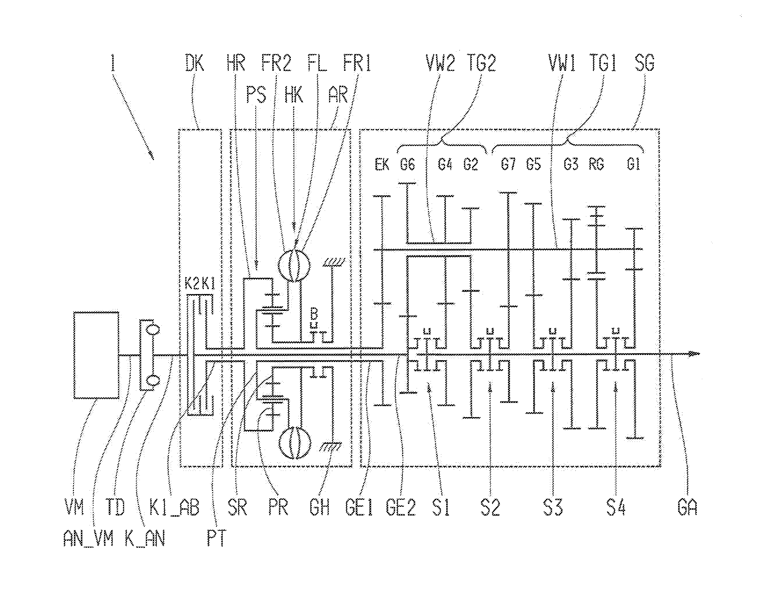
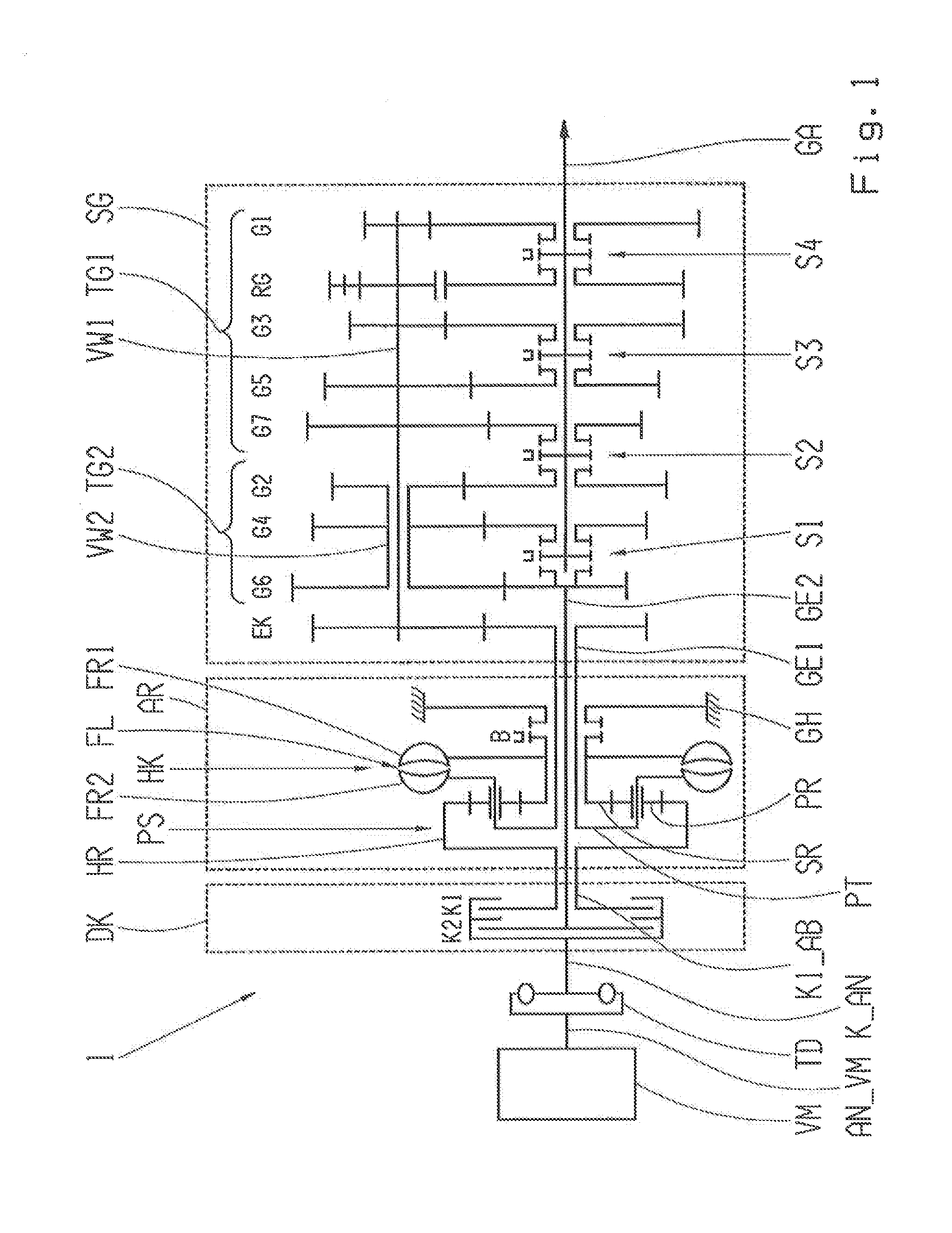
[0076]FIG. 1 shows a drive device for a vehicle, comprising a double clutch transmission 1, which has a multistage, automated manual transmission SG having two sub-transmissions TG1, TG2, one start-up retarder AR, one double clutch DK having two friction clutches K1, K2, one vibration damper TD, and one internal combustion engine VM.

[0077]The manual transmission SG has a countershaft design and comprises, in all, seven forward gears G1, G2, G3, G4, G5, G6, G7 and one reverse gear RG, which can be shifted by means of four double-sided shifting groups S1, S2, S3, S4. Since the design of an auxiliary transmission is known per se and the mode of operation of the individual gearwheels, which are designed as idler gears and fixed gears, of such a transmission is irrelevant to the invention, an explicit description of the individual gearwheels will be omitted, fo...


PUM


Abstract

A drive device for a vehicle having a combustion engine and a multistage manual transmission having first and second sub-transmissions, each of which has a separate input shaft. A first input shaft of the first sub-transmission couples, via a first clutch, the combustion engine or is assigned an electrical machine. A second input shaft of a second sub-transmission couples, via a second clutch, the combustion engine. The first input shaft is additionally assigned a start-up element having at least one hydrodynamic transfer element, which has first and second functional wheels which together form a working chamber. The working chamber can be filled with fluid in order to generate a hydrodynamic transfer torque such that at least one start-up function, affecting the first sub-transmission, can carried out by way of the start-up element.

Description

[0001]This application is a National Stage completion of PCT / EP2013 / 054232 filed Mar. 4, 2013, which claims priority from German patent application serial no. 10 2012 205 823.0 filed Apr. 11, 2012.FIELD OF THE INVENTION[0002]The invention relates to a drive device for a vehicle according to the preamble of claim 1, and to an operating method.BACKGROUND OF THE INVENTION[0003]Drive devices of vehicles, comprising manual transmissions having two sub-transmissions or functionally comparable, separate transmission trains, which can usually be shifted automatically or in an automated manner, are already known. Certain functions of such a drive are usually assigned to only one of the two sub-transmissions, or can only be implemented thereby, and therefore asymmetrical loads can occur on the sub-transmissions, or certain functions are mutually exclusive or are available only with limitations.[0004]In a double clutch transmission, for example, usually one of two input-side power-shift transm...

Claims


Application Information

Patent Timeline
Patent Type & Authority Applications(United States)
IPC IPC(8): F16H47/06F16H61/04F16H3/097B60T1/087F16H3/00
CPCY02T10/6221B60K6/48B60K17/02B60K17/08B60T1/087B60W30/18027F16H3/006F16H3/097F16H47/06B60K2006/4825F16H2061/0414F16H2312/02Y02T10/6252F16H61/0403F16H2200/0082F16H2200/0056Y10S903/915B60T1/062B60T10/02F16D57/04Y02T10/62
Inventor BORNTRAGER, KAIKALTENBACH, JOHANNES
Owner ZF FRIEDRICHSHAFEN AG
Why Eureka
Try Eureka