Lighting device, headlight apparatus using the same, and vehicle using the same

a technology of headlight apparatus and light source, which is applied in the direction of electroluminescent light sources, semiconductor lamps, transportation and packaging, etc., can solve the problems of power supply voltage fluctuation of vehicle batteries, inability to normally switch between low-beam and high-beam, and lighting state of load, etc., and achieve the effect of hysteresis characteristics

Active Publication Date: 2015-03-12
PANASONIC INTELLECTUAL PROPERTY MANAGEMENT CO LTD
View PDF3 Cites 7 Cited by
  • Summary
  • Abstract
  • Description
  • Claims
  • Application Information

AI Technical Summary

Benefits of technology

[0011]According to the present technology, as a condition of switching to the first state where the at least one light emitting element is short-circuited by the bypass unit or the second state where the short-circuiting is opened, the controller is configured to have hysteresis characteristics with the first threshold voltage and the second threshold voltage to be compared with the second power supply voltage. Further, according to the present technology, as a condition of starting the operation of the power converter, the starting voltage to be compared with the first power supply voltage is set to be lower than the first threshold voltage. Therefore, it is possible to normally switch lighting states of the load even when the power supply voltage fluctuates.

Problems solved by technology

However, a power supply voltage of the vehicle battery fluctuates depending on deterioration of the vehicle battery due to the life thereof, or an increase of consumed current.
For this reason, in the lighting device for vehicle as the above conventional example, when the power supply voltage of the vehicle battery fluctuates, there is a possibility that it is impossible to normally switch the low-beam and the high beam, namely, lighting states of a load.

Method used


Image

  • Lighting device, headlight apparatus using the same, and vehicle using the same
  • Lighting device, headlight apparatus using the same, and vehicle using the same
  • Lighting device, headlight apparatus using the same, and vehicle using the same

Examples


first embodiment

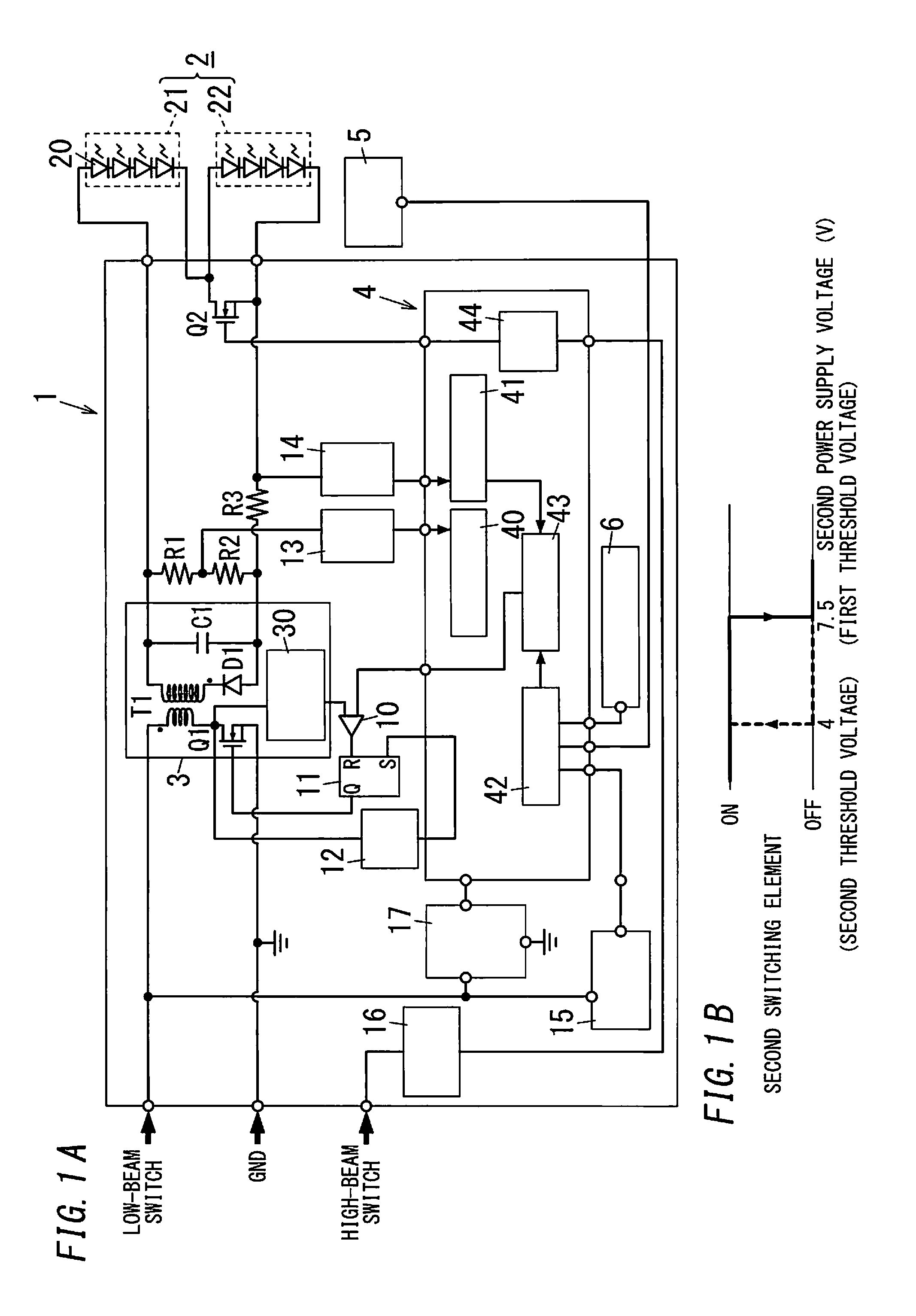
[0028]A lighting device 1 according to the present embodiment includes a power converter 3, a second switching element Q2 (a bypass unit) and a microcomputer 4 (a controller). The power converter 3 is configured to convert a first power supply voltage that is received from a battery 8 (a DC power supply) through a first path 50 (see FIG. 13), and supply an output obtained by the conversion to a load 2 in which a plurality of LEDs 20 (light emitting elements) are connected in series. The second switching element Q2 is configured to short-circuit at least one LED 20 (a second light source unit 22) of the plurality of LEDs 20, as part of the load 2. The microcomputer 4 is configured to control the power converter 3. Further, the microcomputer 4 is configured to control switching on / off of the second switching element Q2 (a first state where the second light source unit 22 is short-circuited by the second switching element Q2, and a second state where the short-circuiting is opened).

[00...

second embodiment

[0063]Hereinafter, a lighting device 1 according to the present embodiment will be described with reference to drawings. Because a basic configuration of the lighting device 1 according to the present embodiment is similar to that of the lighting device 1 according to the First Embodiment, components similar to the First Embodiment are assigned with same reference numerals, and explanations thereof will be appropriately omitted. As shown in FIG. 4, in the lighting device 1 according to the present embodiment, a controller includes a microcomputer 4 that is configured to perform the first control, and a switching circuit 7 that is configured to perform the second control.

[0064]The switching circuit 7 includes a detecting circuit 70 that is configured to detect the second power supply voltage, and a Schmidt trigger circuit 71 that is configured to have hysteresis characteristics with the first threshold voltage and the second threshold voltage. The detecting circuit 70 includes a seri...

third embodiment

[0071]Hereinafter, a lighting device 1 according to the present embodiment will be described with reference to drawings. Because a basic configuration of the lighting device 1 according to the present embodiment is similar to that of the lighting device 1 according to the Second Embodiment, components similar to the Second Embodiment are assigned with same reference numerals, and explanations thereof will be appropriately omitted. The lighting device 1 according to the present embodiment is characterized in that a controller is configured to measure a load voltage of a second light source unit 22 (at least one LED 20, as part of a load 2), and determine that abnormality occurs when the load voltage satisfies a prescribed condition, and then switch on a second switching element Q2 (a bypass unit) (switch to the first state where the second light source unit 22 is short-circuited).

[0072]As shown in FIG. 6, in the lighting device 1 according to the present embodiment, the microcomputer...


PUM


Abstract

A microcomputer is configured to perform a first control and a second control. The first control is of: starting operation of a power converter, when a first power supply voltage exceeds a starting voltage; and stopping the operation of the power converter, when the first power supply voltage is below a maintaining voltage. The second control is of: switching off a second switching element, when a second power supply voltage exceeds a first threshold voltage; maintaining an off-state of the second switching element until the second power supply voltage is below a second threshold voltage; and switching on the second switching element, when the second power supply voltage is below the second threshold voltage.

Description

CROSS-REFERENCE TO RELATED APPLICATIONS[0001]The application is based upon and claims the benefit of priority of Japanese Patent Application No. 2013-187583 filed on Sep. 10, 2013, the entire contents of which are incorporated herein by reference.TECHNICAL FIELD[0002]The disclosure relates generally to lighting devices, headlight apparatuses using the same, and vehicles using the same, and more particularly, to a lighting device which is configured to light a light source that includes a light emitting element such as a light emitting diode, a headlight apparatus using the same, and a vehicle using the same.BACKGROUND ART[0003]Conventionally, the number of vehicles including, as a headlight, an HID (High Intensity Discharged) lamp instead of a halogen lamp had been increased, in order to improve the visibility (brightness). However, recently, due to the improvement of luminous efficiency of an LED (light emitting diode), mass production of vehicles including, as the headlight, the L...

Claims


Application Information

Patent Timeline
Patent Type & Authority Applications(United States)
IPC IPC(8): B60Q1/04H05B33/08H05B44/00
CPCH05B33/0815B60Q1/04B60Q1/0094B60Q1/1415H05B45/382Y02B20/30H05B45/385B60Q1/1423H05B45/48H05B45/54
Inventor SUGANUMA, KAZUTOSHITANAKA, TOSHIFUMIFUKUI, TAKAHIRO
Owner PANASONIC INTELLECTUAL PROPERTY MANAGEMENT CO LTD
Why Eureka
Try Eureka