Synchronization system and frequency divider circuit

Active Publication Date: 2015-03-12
MEGACHIPS
View PDF9 Cites 3 Cited by
  • Summary
  • Abstract
  • Description
  • Claims
  • Application Information

AI Technical Summary

Benefits of technology

The invention provides a synchronization system and a frequency divider circuit that can prevent timing violations and reduce the number of pins needed for connection between different circuits. Additionally, the invention provides a solution for the problem of timing when changing the division ratio of the divided clock. The division ratio detection circuit allows for the efficient and accurate detection of the division ratio of the divided clock, which is useful in various applications such as communication and network systems.

Problems solved by technology

In the conventional synchronization system 80, however, there has been a problem in terms of timing closure.
In addition, there is a disadvantage in terms of the number of pins when mounting the synchronization system 80.
Therefore, timing requirement for changing the first division ratio is very severe.

Method used


Image

  • Synchronization system and frequency divider circuit
  • Synchronization system and frequency divider circuit
  • Synchronization system and frequency divider circuit

Examples


Embodiment Construction

[0048]Hereinafter, a synchronization system and a frequency divider circuit according to one or more embodiments of the invention will be described in detail with reference to the accompanying diagrams.

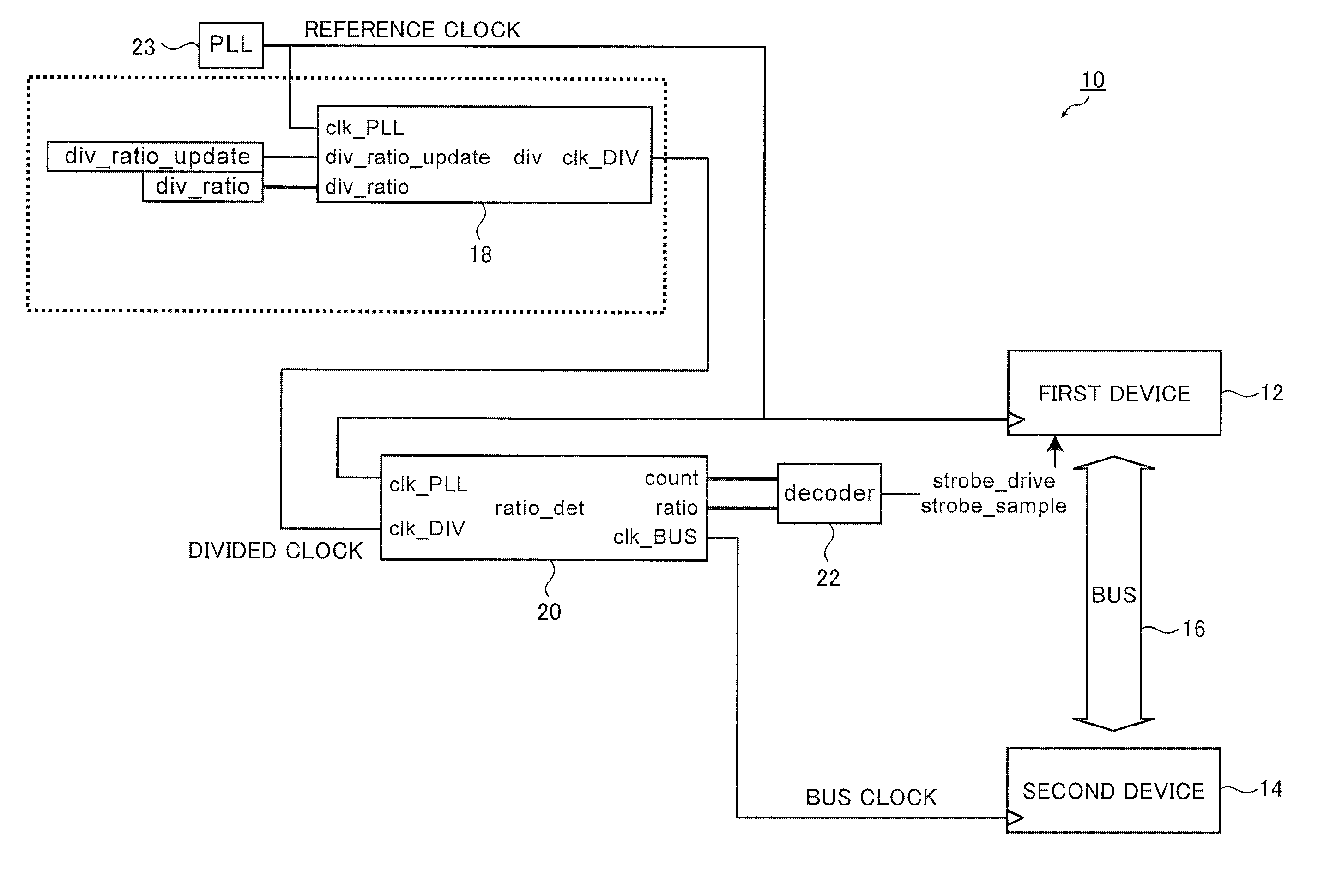
[0049]FIG. 1 is a block diagram showing the configuration of a synchronization system 10 according to one or more embodiments of the invention. The synchronization system 10 shown in FIG. 1 is a synchronization system in which an embodiment of the present invention is applied to the conventional synchronization system 80 shown in FIG. 13.

[0050]The synchronization system 10 includes a first device 12, a second device 14, a frequency divider circuit (div) 18, a division ratio detection circuit (ratio_det) 20, and a decoder 22. In addition, a PLL 23 is also shown in the diagram.

[0051]A reference clock (clk_PLL) is input to the first device 12 from a clock generation circuit, such as the PLL 23, and an input strobe signal (strobe_sample) and an output strobe signal (strobe_drive) are inpu...


PUM


Abstract

In a synchronization system, a frequency divider circuit generates a divided clock by dividing a reference clock in a first division ratio. First and second devices operate in synchronization with the reference clock and the divided clock. A division ratio detection circuit, for each period of the divided clock, detects a division ratio of the divided clock based on a count value counted in synchronization with the reference clock and output the division ratio as a second division ratio. A decoder generates a strobe signal, which is for controlling a timing at which the first device transmits and receives a signal to and from the second device, based on the count value and the second division ratio. The first device communicates with the second device through a bus, which operates in synchronization with the divided clock, based on the strobe signal.

Description

CROSS-REFERENCE TO RELATED APPLICATIONS[0001]The present application claims priority under 35 U.S.C. §119 to Japanese Patent Application No. 2013-186344, filed Sep. 9, 2013. The above application is hereby expressly incorporated by reference, in its entirety, into the present application.BACKGROUND OF THE INVENTION[0002]Embodiments of the invention relate to a synchronization system and a frequency divider circuit that generates a divided clock used in the synchronization system.[0003]FIG. 13 is a block diagram showing an example of the configuration of the conventional synchronization system 80. The synchronization system 80 shown in FIG. 13 includes a first device 82, a second device 84, a frequency divider circuit 88, and a decoder 92.[0004]The first device 82 operates in synchronization with a reference clock (clk_PLL) supplied from a clock generation circuit, such as a phase locked loop (PLL) 93, and the second device 84 operates in synchronization with a divided clock generate...

Claims


Application Information

Patent Timeline
IPC IPC(8): H03K21/02H03L7/24
CPCH03L7/24H03K21/02
Inventor YAMASHITA, KAZUNORI
Owner MEGACHIPS
Why Eureka
Try Eureka