Light guide plate

a technology of light guide plate and light guide plate, which is applied in the direction of instrumentation, lighting and heating apparatus, planar/plate-like light guide, etc., can solve the problems of significant cost increase, increase in color unevenness of outgoing light, and uneven luminance in outgoing light, so as to reduce the unevenness of luminance and color, easy to manufacture, and high light use efficiency

Active Publication Date: 2015-03-12
FUJIFILM CORP
View PDF5 Cites 2 Cited by
  • Summary
  • Abstract
  • Description
  • Claims
  • Application Information

AI Technical Summary

Benefits of technology

[0029]The present invention can provide a large-sized thin light guide plate which is high in light use efficiency, which is capable of emitting light with reduced unevenness in luminance and color and obtaining a so-called convex distribution, that is, such a distribution that an area around the center of the screen is brighter than the periphery as required of a large flat screen liquid crystal television, which is easy to manufacture and which can prevent a cost increase.

Problems solved by technology

However, an increase in size of an edge-lit backlight unit causes a necessity to guide light having entered the light guide plate over longer distances and hence the ratio of the light quantities based on the wavelength varies significantly depending on the distance from the light incidence surface, thus leading to an increase in color unevenness of outgoing light.
It is necessary to perform classification with a very high degree of accuracy in order to adjust the particle size of scattering particles in a specific particle size range, which will lead to a significant cost increase.
In a case where a thin light guide plate is applied, a dot pattern provided on the rear surface may be seen in outgoing light, and there will arise a problem such as occurrence of luminance unevenness in the outgoing light.

Method used


Image

  • Light guide plate
  • Light guide plate
  • Light guide plate

Examples


example 1

[0232]In Example 1, the particle size distribution of scattering particles to be kneaded and dispersed in the light guide plate 30 shown in FIG. 3 was variously changed and the normalized intensity distributions (luminance distributions), the chromaticity distributions and the color differences of outgoing light were determined by computer simulation.

[0233]In Example 1, two particle groups each having a single particle size were mixed and used as scattering particles.

[0234]In the simulation, the material of the transparent resin of the light guide plate and the material of the scattering particles were modeled as PMMA and silicone particles, respectively. This will also apply to all the examples given below.

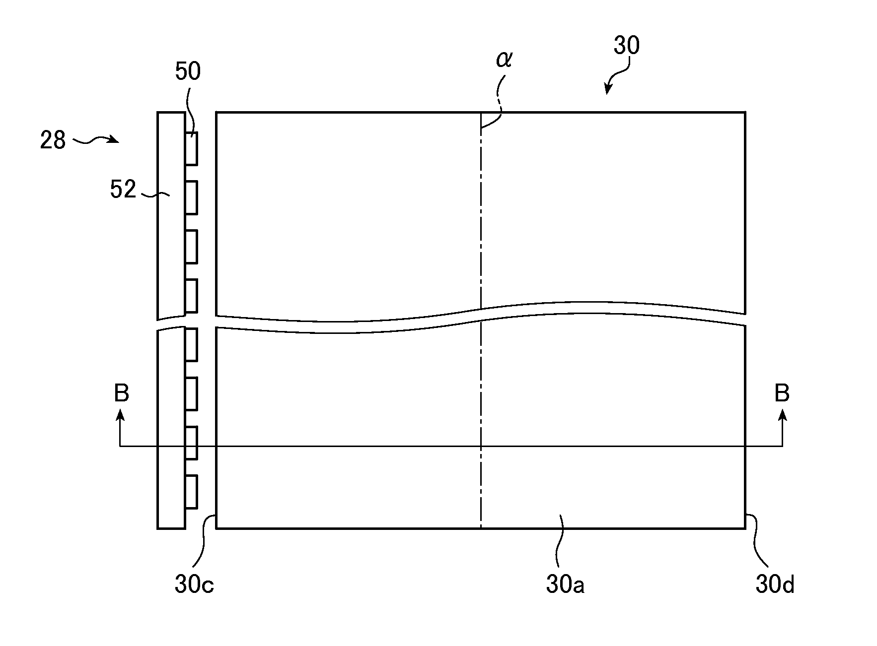
[0235]In Example 1-1, the light guide plate 30 corresponding to a 60-inch screen size was used. More specifically, the length L1g from the first light incidence surface 30c to the opposite lateral surface 30d (length of the light guide plate) was set to 780 mm.

[0236]The thickness...

example 2

[0273]Next, two monodisperse particle groups were mixed and used as scattering particles to determine the intensity distributions of outgoing light, the chromaticity distributions and the color differences.

[0274]The monodisperse particle groups for use in the examples are first described.

[0275]Four types of commercially available silicone particles (TOSPEARL 1100, TOSPEARL 120A, TOSPEARL 130A, and TOSPEARL 145T manufactured by Momentive Performance Materials Inc.) were used as models of monodisperse particle groups. The modeled particle groups are denoted by T1, T2, T3 and T4, respectively.

[0276]The particle size distributions of the particle groups T1, T2, T3 and T4 are shown in FIGS. 16A to 16D, respectively.

[0277]In FIGS. 16A to 16D, the vertical axis indicates the volume fraction (%) and the horizontal axis indicates the particle size (μm).

[0278]T1 has an average particle size of 10.0 μm, T2 an average particle size of 2.0 μm, T3 an average particle size of 3.0 μm, and T4 an ave...

example 3

[0292]In Example 3, the particle groups T1 and T3 were mixed and used as scattering particles.

[0293]In Example 3-1, Example 2-1 was repeated except that the particle groups T3 and T1 were mixed at a ratio of 35:65 (a=0.35) for scattering particles, thereby determining the intensity distributions of blue light, green light and red light, and the distributions of the chromaticities x and y, and the color differences Δx and Δy.

[0294]The results are shown in FIGS. 21A to 21C.

[0295]The color differences Δx and Δy were 0.0048 and 0.0053, respectively.

[0296]In Example 3-2, Example 3-1 was repeated except that the particle groups T3 and T1 were mixed at a ratio of 36.5:63.5 (a=0.365) for scattering particles, thereby determining the intensity distributions of blue light, green light and red light, and the distributions of the chromaticities x and y, and the color differences Δx and Δy.

[0297]The results are shown in FIGS. 22A to 22C.

[0298]The color differences Δx and Δy were 0.0011 and 0.000...


PUM

PropertyMeasurementUnit
particle size distributionaaaaaaaaaa
particle sizeaaaaaaaaaa
particle size distributionaaaaaaaaaa

Abstract

A large-sized thin light guide plate has a first layer on a light exit surface side and a second layer on a rear surface side containing scattering particles at a higher particle concentration than the first layer. Thicknesses of the layers in a direction substantially perpendicular to the light exit surface change to change a combined particle concentration. The scattering particles, obtained by mixing a particle group with an average particle size Ds of less than 7 μm having one or more local maximum values and a particle group with an average particle size Db of more than 7 μm having one or more local maximum values, satisfy 1 μm≦Ds<7 μm, 7 μm<Db≦12 μm and 0.3≦a≦0.5. High light use efficiency, reduction of luminance and color unevenness, a convex brightness distribution and easy manufacture can be achieved.

Description

CROSS-REFERENCE TO RELATED APPLICATIONS[0001]This application is a Continuation of PCT International Application No. PCT / JP2013 / 060945 filed on Apr. 11, 2013 which claims priority under 35 U.S.C. §119(a) to Japanese Application No. 2012-118402 filed on May 24, 2012. Each of the above application(s) is hereby expressly incorporated by reference, in its entirety, into the present application.BACKGROUND OF THE INVENTION[0002]The present invention relates to a light guide plate for use in a planar lighting device that may be used for backlight of a liquid crystal display.[0003]A liquid crystal display uses a planar lighting device (a backlight unit) which illuminates a liquid crystal display panel by irradiation of light from the back side of the liquid crystal display panel. The backlight unit is configured using a light guide plate for diffusing light emitted from an illumination light source to illuminate the liquid crystal display panel and parts such as a prism sheet and a diffusio...

Claims


Application Information

Patent Timeline
Patent Type & Authority Applications(United States)
IPC IPC(8): F21V8/00G02F1/1335
CPCG02F1/133524G02B6/0011G02B6/0041G02B6/0046G02B6/005G02B6/0061G02B6/0076G02B6/0058
Inventor IWASAKI, OSAMU
Owner FUJIFILM CORP
Why Eureka
Try Eureka