X-ray imaging system

a technology of x-ray imaging and x-ray generating device, which is applied in the direction of material analysis using wave/particle radiation, instruments, nuclear engineering, etc., can solve the problems of large geometric unsharpness effect, high requirements for mechanical accuracy and stability of x-ray generating device, and similar problems

Inactive Publication Date: 2015-03-12
CANON KK
View PDF4 Cites 42 Cited by
  • Summary
  • Abstract
  • Description
  • Claims
  • Application Information

AI Technical Summary

Problems solved by technology

In many phase imaging methods, there are similar problems.
Furthermore, in some of the phase imaging methods, since a certain distance is required between the test object and an X-ray detector, there is a tendency that the effect of geometric unsharpness becomes large.
However, in general, the smaller the size of an X-ray source becomes, the higher the requirements for mechanical accuracy and stability of an X-ray generating device become, and the smaller the X-ray generating amount per unit time becomes.
Therefore, there is a problem in that an attempt of making the size of an X-ray source smaller causes increase in device cost and increase in imaging time, which makes the device impractical.

Method used


Image

  • X-ray imaging system
  • X-ray imaging system
  • X-ray imaging system

Examples


first embodiment

[0027]In a first embodiment of the present invention, a general case where the present invention is applied to imaging on the basis of detection of an X-ray transmittance distribution of a test object is described.

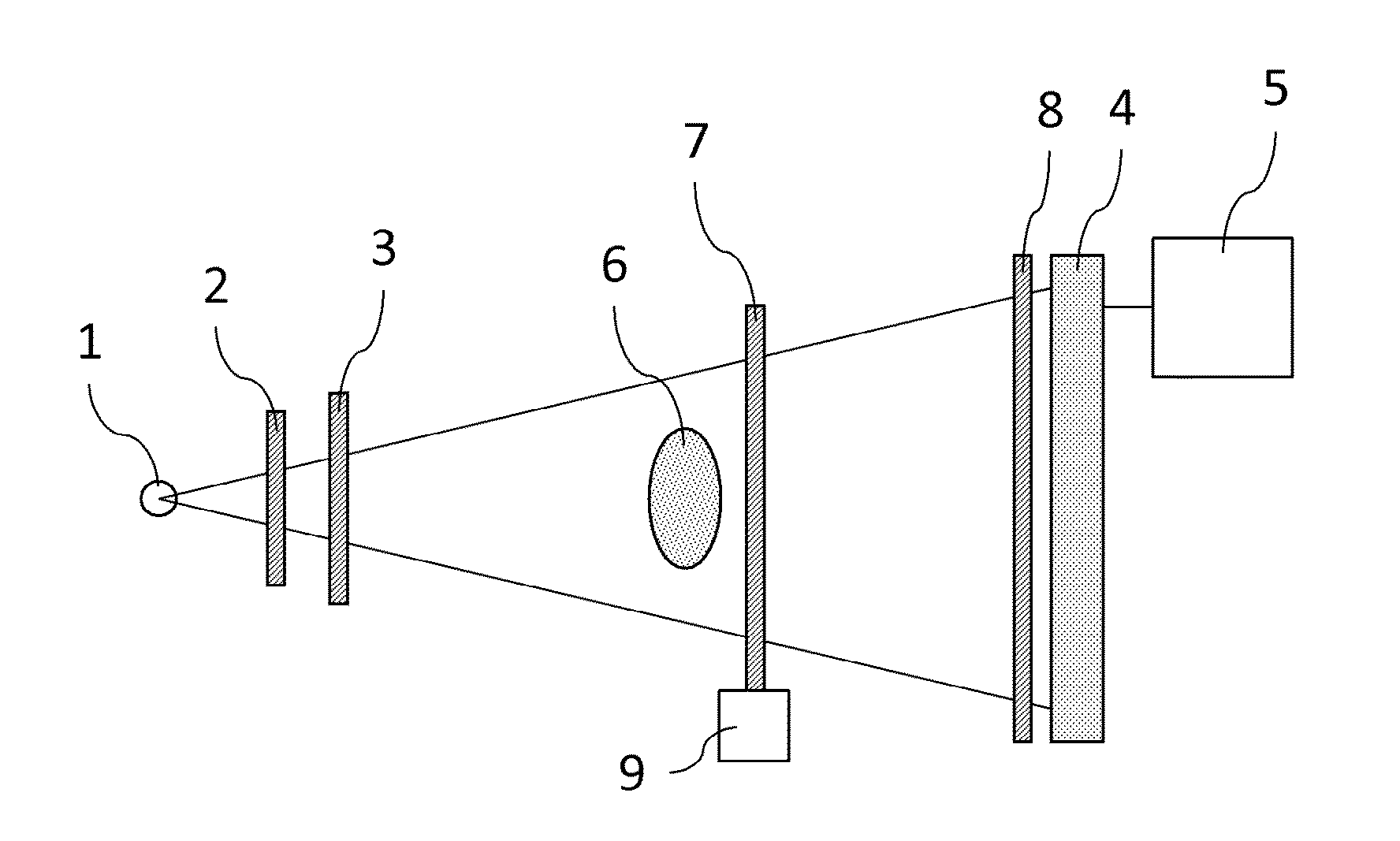
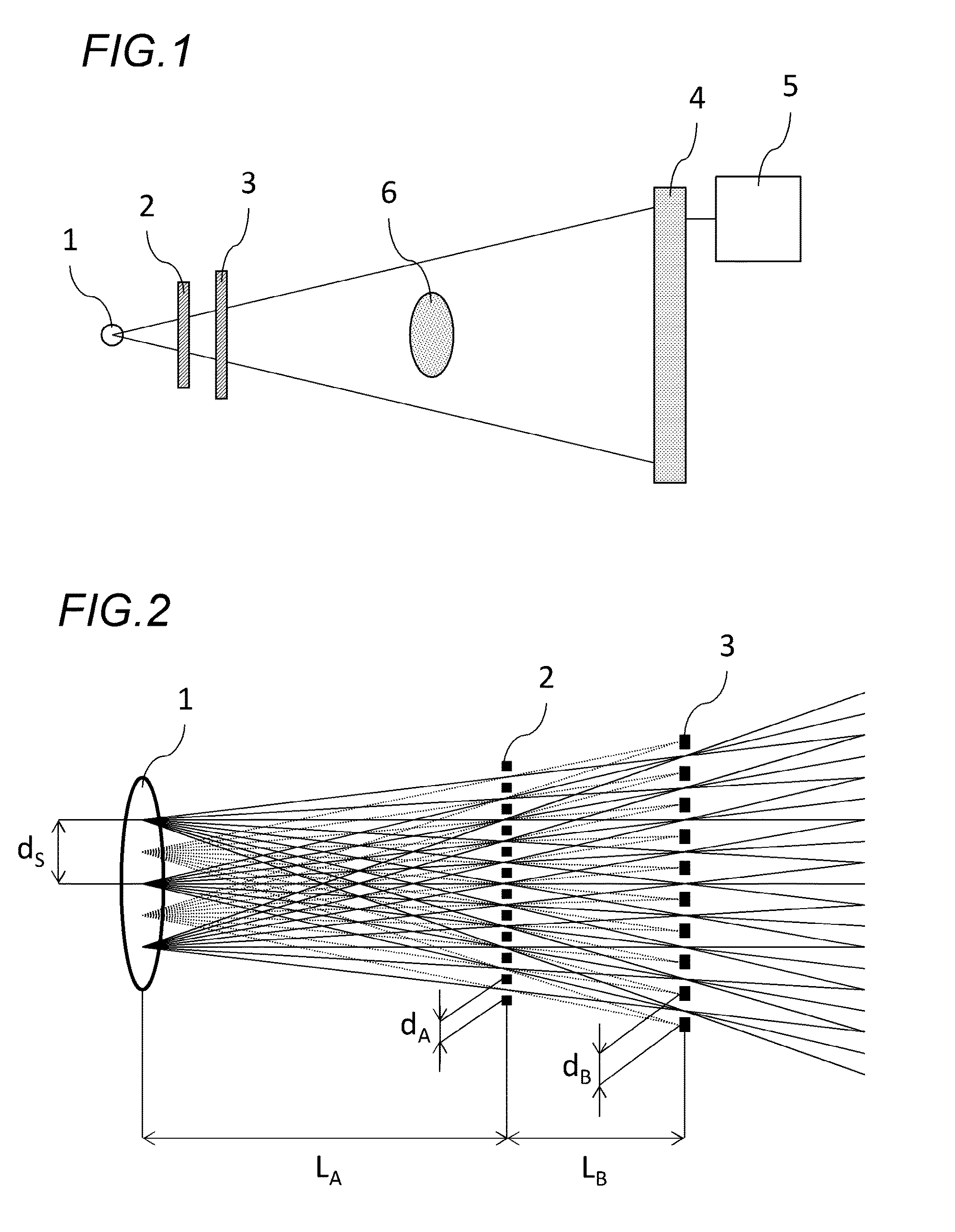
[0028]FIG. 1 is a view illustrating a configuration example of an X-ray imaging system of a first embodiment of the present invention. In FIG. 1, the X-ray imaging system includes: an X-ray source 1, a first grating 2, a second grating 3, an X-ray detector 4, and a processing device 5. The first grating 2 and the second grating 3 are disposed between the X-ray source 1 and a test object 6. An X-ray generated from the X-ray source 1 is transmitted through the test object 6 after transmitting the first grating 2 and the second grating 3, and is incident on an X-ray detector 4. The X-ray detector 4 detects an X-ray intensity distribution (or, a test object image) incident on the detection plane, and transmits the detected test object image information to the processing device...

second embodiment

[0043]In a second embodiment of the present invention, a case where the present invention is applied to a so-called Talbot interferometer is described.

[0044]The Talbot interferometer is a type of interferometer that uses a G1 grating for diffracting an X-ray that is transmitted through a test object, uses a G2 grating disposed at a position where an interference fringe (called a self-image) of the X-ray that is transmitted through the G1 grating is formed, and observe a moire fringe generated by the interference fringe and the G2 grating. Since the self-image of the G1 grating is deformed according to a deformation of a wavefront of the X-ray that is transmitted through the test object, phase information of the X-ray that is transmitted through the test object is obtained by analyzing an image of moire fringe deformation. When used in a condition where sufficient coherence for obtaining an interference fringe is not obtained because an X-ray source is too large, a method in which, b...

example 1

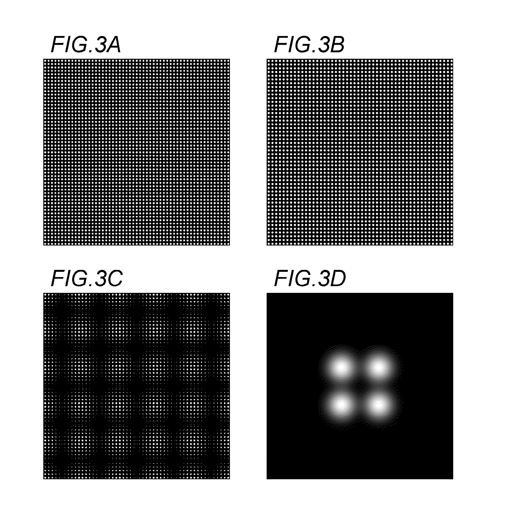
[0053]Example 1 is a specific example of a first embodiment. An X-ray source 1 is an X-ray generating part on an anode of a rotating anode X-ray tube. An anode material is molybdenum, and is used under a tube voltage of 30 kV. An apparent shape of the X-ray source 1 is a shape close to a square having a side length of 600 μm. The first grating 2 and the second grating 3 are both gold gratings of 100 μm in thickness, and have square grating shaped aperture patterns as illustrated in FIG. 3A and FIG. 3B. A period dA of an aperture of the first grating 2 is 10.000 μm, an aperture shape is a circle of 5.642 μm in diameter. On the other hand, a period dB of an aperture of the second grating 3 is 10.345 μm, an aperture shape is a circle of 5.837 μm in diameter. The X-ray detector 4 is a flat panel detector, a pixel size is 50 μm.

[0054]A disposition of each constituent is similar to FIG. 1. A distance LA between the X-ray source 1 and the first grating 2 is 150.00 mm. A distance LB between...


PUM

PropertyMeasurementUnit
dAaaaaaaaaaa
dAaaaaaaaaaa
side lengthaaaaaaaaaa

Abstract

An X-ray imaging system includes: a micro X-ray source array formation part configured to form a micro X-ray source array by partially shielding an X-ray emitted from an X-ray source; and an X-ray detector configured to detect an X-ray transmitted through a test object. The micro X-ray source array formation part includes a plurality of gratings disposed between the X-ray source and the X-ray detector. A ratio of X-rays transmitted through all of the plurality of gratings to X-rays generated from the X-ray source varies depending on a position of an X-ray generating point on the X-ray source, and the micro X-ray source array formation part forms a micro X-ray source array of a pattern in accordance with the variation of the ratio of the transmitted X-rays.

Description

BACKGROUND OF THE INVENTION[0001]1. Field of the Invention[0002]The present invention relates to an X-ray imaging system.[0003]2. Description of the Related Art[0004]In a general X-ray imaging method, an image based on a transmittance distribution of a test object is obtained by irradiating the test object with an X-ray generated from an X-ray source and detecting the intensity distribution of the transmitted X-ray. In recent years, a method (phase imaging method) in which an image of a test object is taken by using information of a phase shift when an X-ray is transmitted through the test object has been researched and developed.[0005]In a general X-ray imaging method, when a size of an X-ray source is too large, there are cases where sharpness of a test object image is reduced by an effect of so-called geometric unsharpness. In many phase imaging methods, there are similar problems. Furthermore, in some of the phase imaging methods, since a certain distance is required between the...

Claims


Application Information

Patent Timeline
Patent Type & Authority Applications(United States)
IPC IPC(8): G01N23/20G21K1/06G01N23/207
CPCG01N23/20075G21K1/067G01N23/207G01N2223/056G01N2223/204G01N2223/316
Inventor HANDA, SOICHIRO
Owner CANON KK
Why Eureka
Try Eureka