Insert and Method of Attaching Insert to Structure

a technology of insert and structure, which is applied in the direction of machines/engines, sustainable manufacturing/processing, and final product manufacturing, etc., can solve the problems of increasing warping in the cross-nut hole and/or the root cylinder, delamination near the insert, and extremely difficult to ensure the thorough filling of the space around the insert, etc., to achieve the effect of long service life and increased warping

Inactive Publication Date: 2015-03-12
WEI7 LLC
View PDF14 Cites 11 Cited by
  • Summary
  • Abstract
  • Description
  • Claims
  • Application Information

AI Technical Summary

Benefits of technology

[0007]The inventor has noticed several problems associated with conventional methods for attaching a wind turbine blade to a wind turbine hub. Such problems are also suffered in other industries and, as such, are not limited to the wind turbine industry. For example, when T-bolts are used, relatively large compressive stresses may be present in the root near the cross-nuts of the T-bolts. These stresses may lead to failure, for example by cleaving of fibers near the cross-nuts. To alleviate this problem, a larger diameter cross-nut may be used, but this increases the perforations of the root which may result in increased warping in the cross-nut holes and / or root cylinder when the structure is subjected to loads. With regard to laminating inserts in place, this process results in a root having voids created near the inserts which act as stress concentrators leading to delamination near the inserts. With regard to bonding metal inserts, it is extremely challenging to ensure thorough fill of the space around the insert without macroscopic voids created by trapped air. Macroscopic voids are to be distinguished from microscopic voids due to air entrained into the adhesive due to the mixing process, the latter being accounted in the nominal properties of the adhesive. Macroscopic voids create stress concentrations when the structure and insert are subjected to loads. The method has a second short-coming in that it can be challenging to fixture the insert concentrically in the hole to ensure a uniform bond thickness. Nonuniform bond thickness can also create stress concentrations. Stress concentrations can cause premature failure of the part.
[0008]With the above in mind, the inventor has set out to design a method which may be used to embed an insert, for example, a female-threaded insert, into a structure, for example, a composite structure, that does not suffer the aforementioned problems. As a result, the inventor has developed a novel and nonobvious insert, system, and method for bonding an insert, for example, a female-threaded metal insert, into a composite structure. Such a method is useful in various industries. For example, the novel method may be used to connect a wind turbine blade to a hub of a wind turbine. Application to the wind turbine industry and wind turbine structures is not intended to be a limiting feature of the invention since the invention may be applied to a variety of industries and / or structures. For example, other applications include, but are not limited to, the aerospace, automobile, construction, and / or boating industries or any industry where it is desired to bond an insert into a structure.
[0009]Example embodiments of the invention include an insert. In example embodiments the insert may be placed in a cavity formed in a structure, for example, a composite structure. In example embodiments, various sealing members may be provided to make the hole an airtight chamber. In example embodiments, a vacuum may be applied to the hole to remove air therefrom. Under vacuum, an adhesive may be applied inside the cavity to bond the insert therein. Because the adhesive is applied under a vacuum, macroscopic voids in the adhesive may be eliminated thereby leading to a bond having a relatively long service life in comparison to the conventional art.

Problems solved by technology

The inventor has noticed several problems associated with conventional methods for attaching a wind turbine blade to a wind turbine hub.
Such problems are also suffered in other industries and, as such, are not limited to the wind turbine industry.
These stresses may lead to failure, for example by cleaving of fibers near the cross-nuts.
To alleviate this problem, a larger diameter cross-nut may be used, but this increases the perforations of the root which may result in increased warping in the cross-nut holes and / or root cylinder when the structure is subjected to loads.
With regard to laminating inserts in place, this process results in a root having voids created near the inserts which act as stress concentrators leading to delamination near the inserts.
With regard to bonding metal inserts, it is extremely challenging to ensure thorough fill of the space around the insert without macroscopic voids created by trapped air.
The method has a second short-coming in that it can be challenging to fixture the insert concentrically in the hole to ensure a uniform bond thickness.
Stress concentrations can cause premature failure of the part.

Method used


Image

  • Insert and Method of Attaching Insert to Structure
  • Insert and Method of Attaching Insert to Structure
  • Insert and Method of Attaching Insert to Structure

Examples


Embodiment Construction

[0044]Example embodiments will now be described more fully with reference to the accompanying drawings, in which example embodiments of the invention are shown. The invention may, however, be embodied in different forms and should not be construed as limited to the example embodiments set forth herein. Rather, these example embodiments are provided so that this disclosure will be thorough and complete, and will fully convey the scope of the invention to those skilled in the art. In the drawings, the sizes of components may be exaggerated for clarity.

[0045]In this application, it is understood that when an element or layer is referred to as being “on,”“attached to,”“connected to,” or “coupled to” another element or layer, it can be directly on, directly attached to, directly connected to, or directly coupled to the other element or layer or intervening elements that may be present. In contrast, when an element is referred to as being “directly on,”“directly attached to,”“directly con...


PUM

PropertyMeasurementUnit
structureaaaaaaaaaa
thicknessaaaaaaaaaa
compressive stressesaaaaaaaaaa

Abstract

Example embodiments relate to an insert and a method for attaching the insert to a structure. In example embodiments the structure may be comprised of a composite material, a metal, and a ceramic.

Description

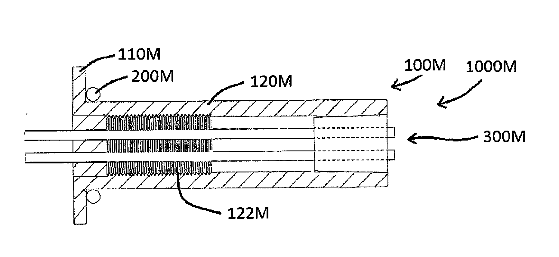
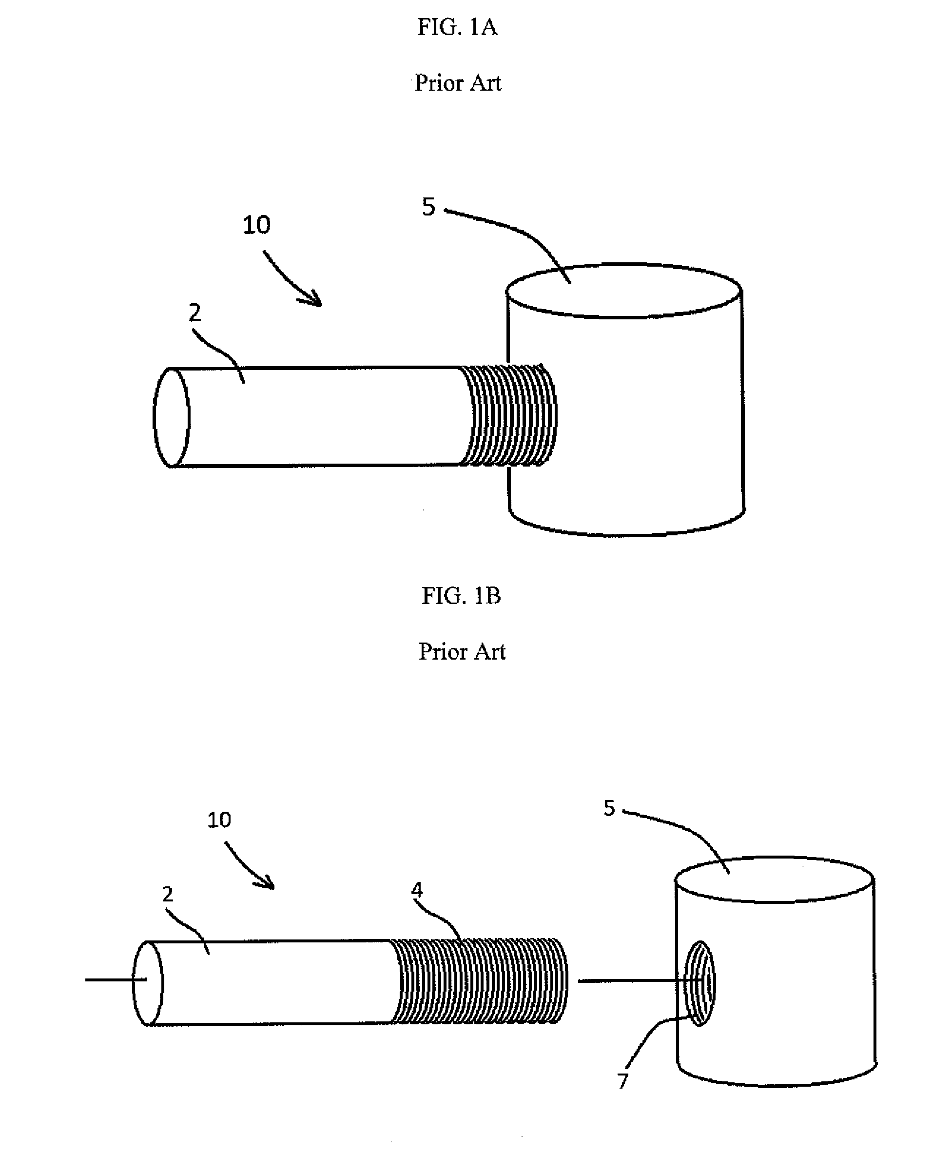
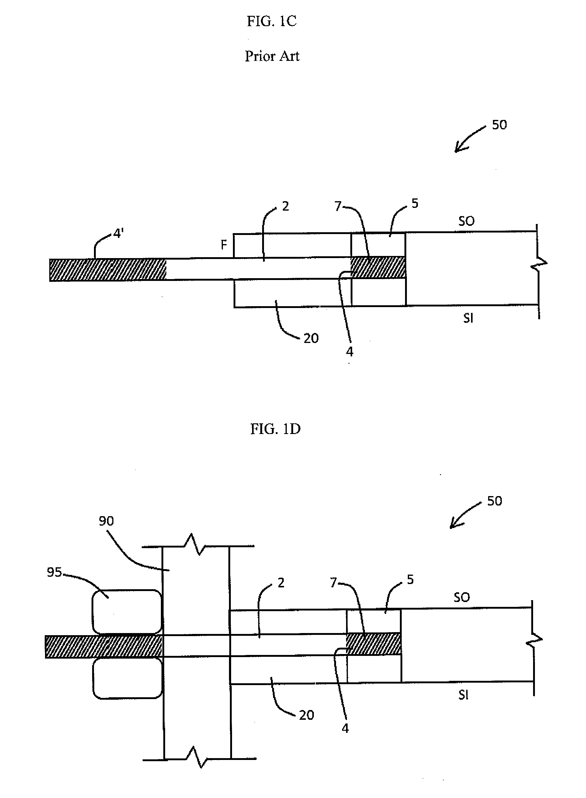
BACKGROUND[0001]1. Field[0002]Example embodiments relate to an insert and a method of attaching the insert to a structure.[0003]2. Description of the Related Art[0004]In the wind turbine industry, T-bolts are often used to attach a wind turbine blade to a hub. FIGS. 1A and 1B are views of a conventional T-bolt 10. As shown in FIGS. 1A and 1B, the conventional T-bolt 10 includes a threaded stud 2 having threads 4 at a first end thereof and a cross-nut 5 having a threaded hole 7. In the prior art, the hole 7 may be sized to receive the threaded end of the stud 2 so that the threads 4 of the stud 2 engage the threads of the hole 7. The threads of the stud 2 and the cross-nut 5 may be engaged with one another simply by rotating the stud 2 with respect to the cross-nut 5 as is well known in the art.[0005]FIG. 1C is a partial cross-section view of a wind turbine blade 50 illustrating a T-bolt arranged in a root 20 thereof. In the prior art, the T-bolt may be installed by drilling a first ...

Claims


Application Information

Patent Timeline
Patent Type & Authority Applications(United States)
IPC IPC(8): F16B11/00
CPCF16B11/006B29C65/4815B29C65/483B29C65/4835B29C65/544B29C66/126B29C66/53B29C66/721B29L2031/085F03D1/0658F03D1/0675F05B2260/301Y02E10/72Y10T403/471Y10T403/477Y02P70/50
Inventor RAINA, AMOOLWULLENSCHNEIDER, TEEYANA S.BARNHART, RYAN MICHAELWETZEL, KYLE K.YANG, CHRIS
Owner WEI7 LLC
Why Eureka
Try Eureka