Control device for legged mobile robot

a mobile robot and control device technology, applied in the field of legged mobile robot control devices, can solve the problems of large displacement of joints, such as the ankle joints or the like of the supporting legs, and achieve the effect of increasing the size or the weight of the actuator and preventing excessive displacement of joints of legs

Active Publication Date: 2015-03-12
HONDA MOTOR CO LTD
View PDF11 Cites 39 Cited by
  • Summary
  • Abstract
  • Description
  • Claims
  • Application Information

AI Technical Summary

Benefits of technology

[0014]Then, when the moment thus applied to a joint is large, since a required driving force of an actuator for driving the joint becomes large, there is a disadvantage of increasing the size or the weight of the actuator.
[0015]The present invention has been made in view of the above background, and it is an object thereof to provide a control device capable of moving a robot over steps having various heights while preventing excessive displacement of a joint of a leg of the legged mobile robot.

Problems solved by technology

Further, for example, when the robot is caused to go down downward stairs having a relatively high step height, the displacement amount of a joint, such as the ankle joint or the like of the supporting leg, becomes large at the time of the landing of the free leg on the lower tread surface.

Method used


Image

  • Control device for legged mobile robot
  • Control device for legged mobile robot
  • Control device for legged mobile robot

Examples


Embodiment Construction

[0046]One embodiment of the present invention will be described below with reference to FIG. 1 to FIG. 10.

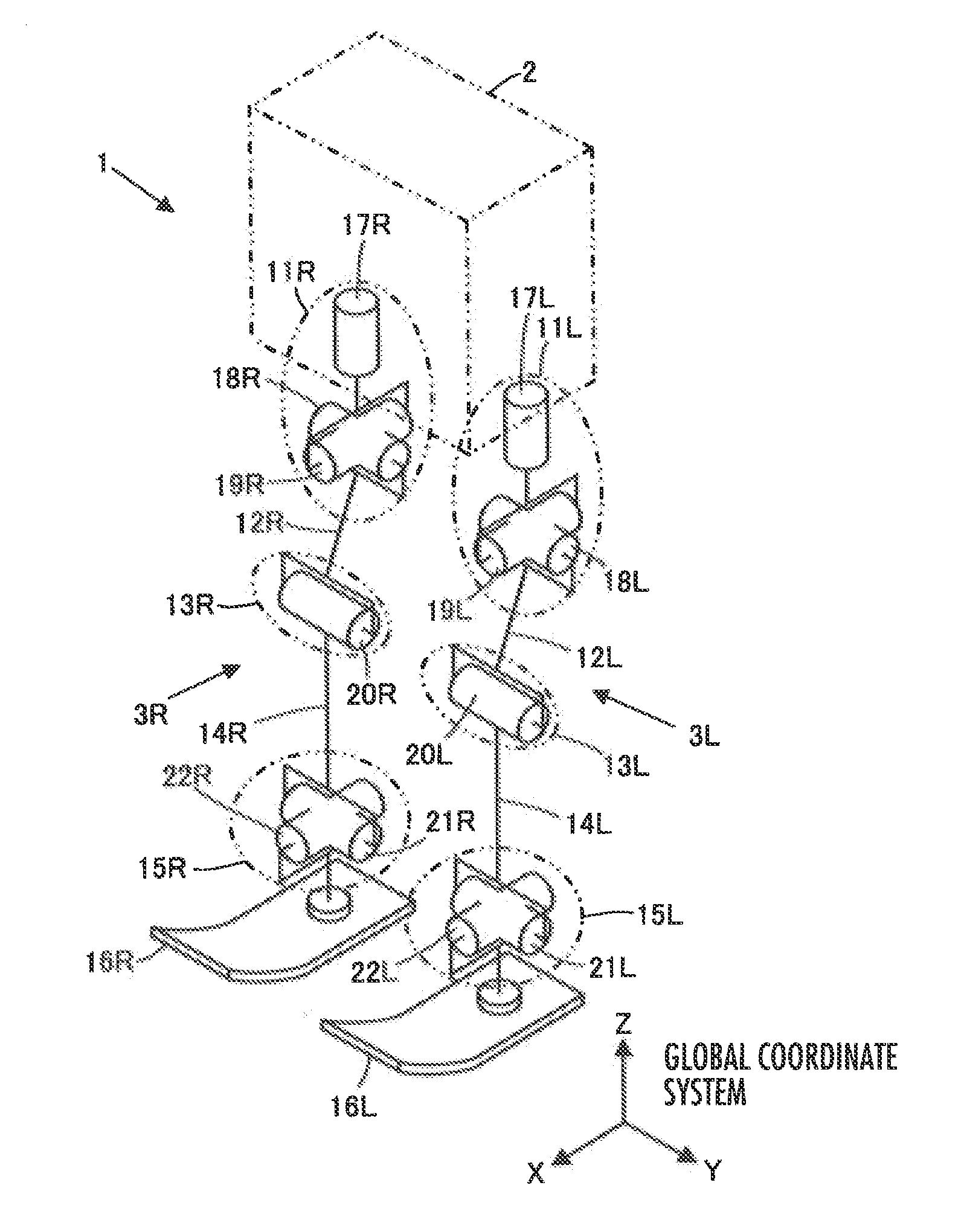
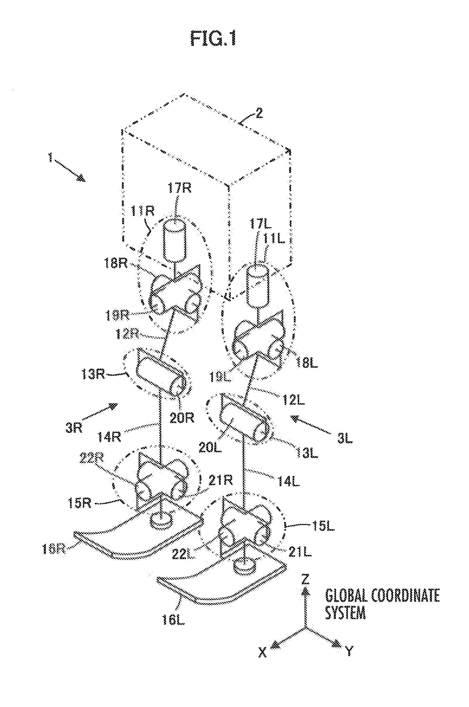
[0047]Referring to FIG. 1, a legged mobile robot 1 (hereinafter simply called a robot 1) of the embodiment is a bipedal walking robot having a body 2 corresponding to the upper body of the robot 1, a pair of (two) right and left legs 3R and 3L extended from the body 2.

[0048]In the description of the embodiment, the symbol “R” is added to a variable indicative of the right member toward the front side of the robot 1, and the symbol “L” is added to a variable indicative of the left member toward the front side of the robot 1. Note that the symbols “R” and “L” may be omitted when it is not necessary to distinguish between the right side and the left side clearly.

[0049]The legs 3R and 3L have the same structure as each other. Specifically, each leg 3 includes, as multiple element links that make up the leg 3, a thigh 12 connected to the body 2 through a hip joint 11, a shank 14 conn...


PUM


Abstract

A setting unit 33 configured to set a first landing permissible region in order to ground a free leg side foot 16 within an upper tread surface or a lower tread surface of a step existing ahead of a legged mobile robot 1 in a traveling direction, and a setting unit 34 configured to set a second landing permissible region in order to ground the free leg side foot 16 on an edge of the upper tread surface or the lower tread surface are provided to switch landing permissible regions for movement control of the robot 1 according to a step height.

Description

BACKGROUND OF THE INVENTION[0001]1. Field of the Invention[0002]The present invention relates to a control device for a legged mobile robot such as a bipedal walking robot.[0003]2. Description of the Related Art[0004]For example, when a bipedal walking robot is caused to go up and down stairs, a foot at the distal end of a free leg is usually landed on a stair tread surface to place the entire or substantially the entire foot on the stair tread surface (the upper tread surface on upward stairs or the lower tread surface on downward stairs) (for example, see Japanese Patent Application Publication No. H6-63876 and Japanese Patent Application Publication No. 2003-340763).[0005]In this case, the landing position targeted for the foot of the free leg is usually determined to prevent the foot in the landing position from coming too close to both edges and the depth end of the tread surface.SUMMARY OF THE INVENTION[0006]In order to move a legged mobile robot such as a bipedal walking robo...

Claims


Application Information

Patent Timeline
Patent Type & Authority Applications(United States)
IPC IPC(8): B25J9/16
CPCB25J9/1633Y10S901/01Y10S901/29Y10S901/28B62D57/032B62D57/024
Inventor KANEKO, HIROYUKIKUROSU, CHIHIRO
Owner HONDA MOTOR CO LTD
Why Eureka
Try Eureka