Screen printer and component mounting line

a technology of component mounting and screen printer, which is applied in the field of screen printer, can solve the problems of large screen printer, increased cost, and complex structure of screen printer, and achieve the effect of reducing cost, simple configuration, and reducing the amount of paste wasted

Inactive Publication Date: 2015-03-19
PANASONIC INTELLECTUAL PROPERTY MANAGEMENT CO LTD
View PDF4 Cites 17 Cited by
  • Summary
  • Abstract
  • Description
  • Claims
  • Application Information

AI Technical Summary

Benefits of technology

[0012]In the aspects of the present invention, a paste print is formed as the print head reciprocates between the first or second area and the start position located between the first area and the second area on the mask. The single print head serves as both of a print head for printing with the first pattern and printing with the second pattern. Consequently, it is possible to perform, with a simple configuration, printing on plural kinds of boards in parallel so as to correspond with the two-lane component mounter installed on a downstream side. Furthermore, since the print head reciprocates, that is, moves from the start position located between the first area and the second area and returns to the original position (start position), residual paste can be used for the next printing irrespective of whether printing has been performed using the first pattern or the second pattern. Therefore, the amount of paste wasted is reduced and hence the cost can be reduced accordingly. Still further, since the paste on the mask is returned to a region between the first area and the second area on the mask when a printing operation has been completed, printing operations can be started immediately even if different kinds of boards are carried in in random order (i.e., a printing operation can be started immediately irrespective of whether a board contacts the first area or the second area).

Problems solved by technology

However, the screen printer becomes large, and cost is increased.
Therefore, the structure of the screen printer becomes complex.
Further, because of the two print heads, they waste a larger amount of paste than a screen printer with a single print head, and cost is increased in this respect.

Method used


Image

  • Screen printer and component mounting line
  • Screen printer and component mounting line
  • Screen printer and component mounting line

Examples


first embodiment

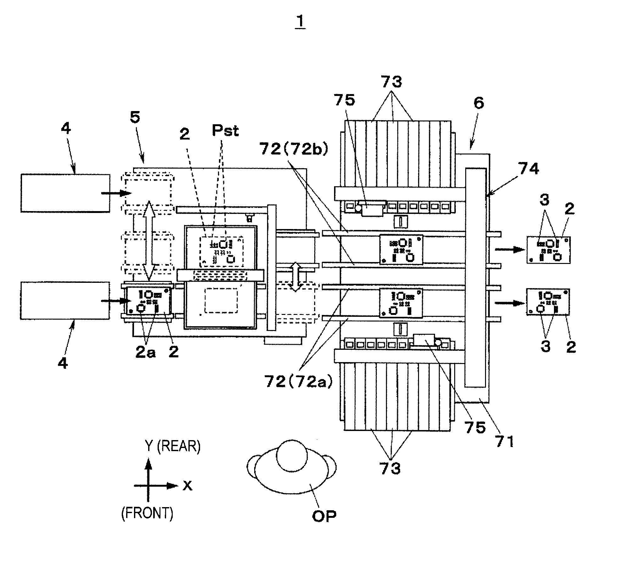
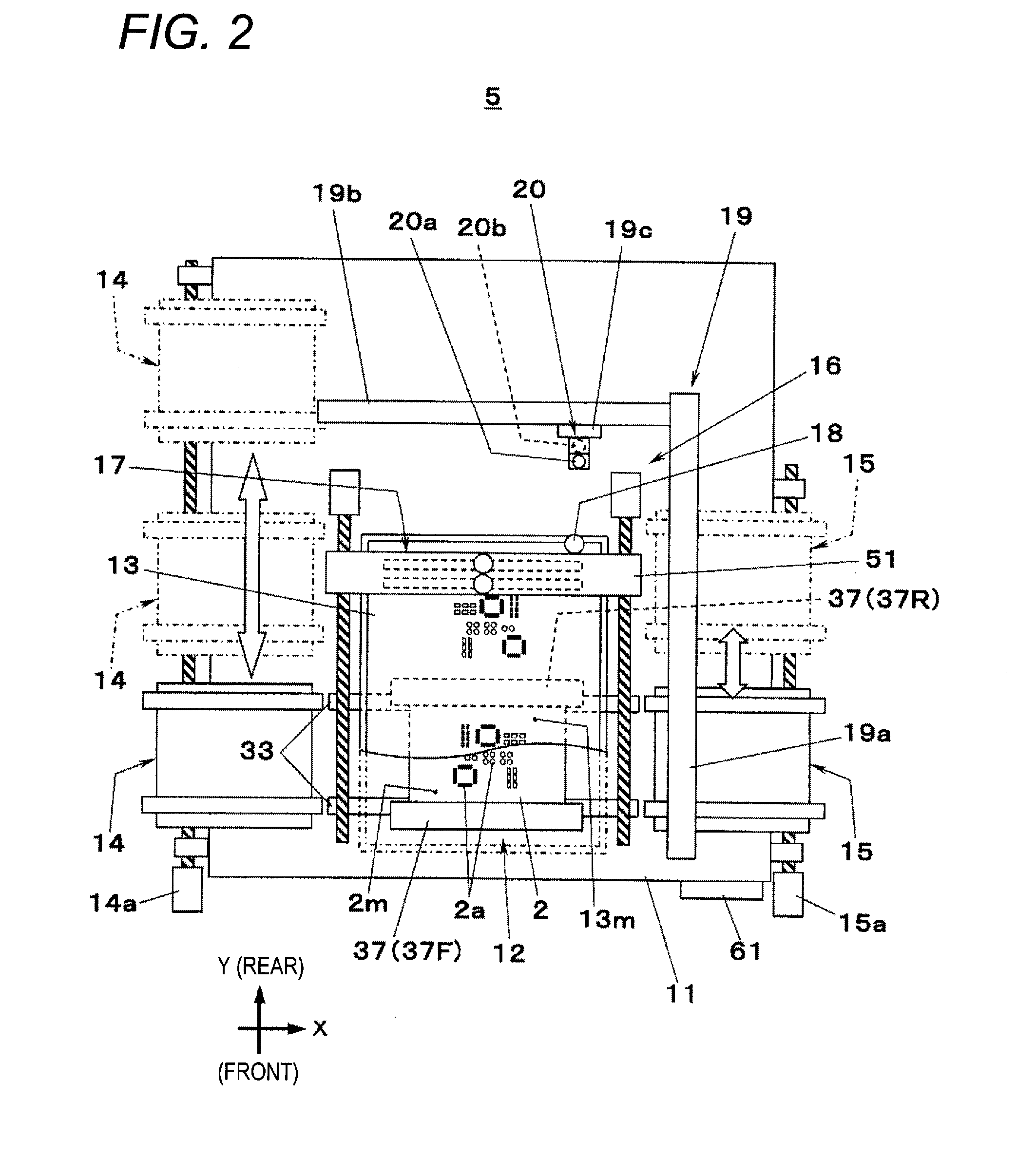
[0028]FIG. 1 shows a component mounting line 1 according to a first embodiment of the invention. The component mounting line 1, which is to manufacture component-mounted boards by mounting a component 3 on each board 2, includes a screen printer 5 for forming, by screen printing, paste layers Pst such as solder layers on electrodes 2a of each board 2 supplied from one of board supply units 4 and a component mounter 6 for mounting a component 3 on each board 2 on which paste layers Pst have been formed by the screen printer 5. In the component mounting line 1 according to the first embodiment, each board 2 flows left to right in FIG. 1 (in the left to right direction as viewed by an operator OP). This direction in a horizontal plane is defined as the positive X-axis direction. The direction that is perpendicular to the X-axis direction in the horizontal plane is defined as the Y-axis direction, and the top-bottom direction is defined as the Z-axis direction. In the first embodiment, ...

second embodiment

[0058]Next, a second embodiment of the invention will be described. FIG. 12 shows a component mounting line 101 according to the second embodiment of the invention. Similar to the component mounting line 1 according to the first embodiment, the component mounting line 101 includes a screen printer 105 and a component mounter 106. In FIGS. 12 and 13, constituent elements of the screen printer 105 having the same ones in the screen printer 5 according to the first embodiment are given the same reference symbols as the latter. In FIG. 12, constituent elements of the component mounter 106 having the same ones in the component mounter 6 used in the first embodiment are given the same reference symbols as the latter.

[0059]The screen printer 105 according to the second embodiment is configured basically in the same manner as the screen printer 5 according to the first embodiment, and different from the latter in the following points. In the screen printer 105 according to the second embodi...


PUM

PropertyMeasurementUnit
areaaaaaaaaaaa
areasaaaaaaaaaa
structureaaaaaaaaaa

Abstract

A screen printer includes: a mask having a first area formed with a first pattern and a second area formed with a second pattern; and a print head which forms a past printing on a board and is movable on the mask. When a paste print is formed using the first pattern, the print head moves from a start position located between the first area and the second area to the first area and then returns to the start position. When a paste print is formed using the second pattern, the print head moves from the start position to the second area and then returns to the start position.

Description

BACKGROUND[0001]1. Technical Field[0002]An aspect of the present invention relates to a screen printer for forming paste prints on boards using a mask formed with patterns. Another aspect of the invention relates to a component mounting line including the screen printer.[0003]2. Background Art[0004]There is a screen printer which performs, in parallel, screen printing operations for forming prints of paste such as solder on plural kinds of boards and successively supplies resulting boards to a two-lane component mounter (i.e., a component mounter equipped with two board conveying lanes) installed on a downstream side. JP-A-2009-070867 describes a screen equipped with two printing units. Each of the printing units includes a board holding unit and a mask and performs a screen printing operation. However, the screen printer becomes large, and cost is increased. JP-A-2011-143640 describes a screen printer including a single printing unit. The printing unit includes a mask having two pa...

Claims


Application Information

Patent Timeline
Patent Type & Authority Applications(United States)
IPC IPC(8): B32B38/00H05K3/36H05K3/12B32B37/00B32B39/00
CPCB32B38/145B32B37/0046B32B39/00B32B2457/08H05K3/368B32B2307/202H05K3/1225H05K3/1216B41F15/0881B41F15/423H05K3/3485
Inventor MANTANI, MASAYUKIMURAKAMI, TOSHIYUKI
Owner PANASONIC INTELLECTUAL PROPERTY MANAGEMENT CO LTD
Why Eureka
Try Eureka