Network node connection configuration

a network node and configuration technology, applied in data switching networks, multiplex communication, digital transmission, etc., can solve the problems of dictating at least a portion of implementation cost, limited to a 100 meter reach, etc., to simplify connections, reduce cost components, and facilitate connectivity for network devices

Active Publication Date: 2015-03-19
HEWLETT-PACKARD ENTERPRISE DEV LP
View PDF11 Cites 24 Cited by
  • Summary
  • Abstract
  • Description
  • Claims
  • Application Information

AI Technical Summary

Benefits of technology

[0012]The present disclosure provides a system and method for connectivity of network devices that permits simplified connections for realizing complex networking topologies. The connectivity for the network devices can be achieved using lower cost components. The disclosed system and method permits cabling to be simplified and permits reduced cost cabling to be used to make connections while providing implementations of complex networking topologies. The disclosed system and method assist in simplifying connectivity implementation, so that complex networking topologies can be realized faster and with greater reliability.
[0024]According to another aspect, one or more connector positions can each be coupled to a bidirectional fiber construct. The bidirectional construct can transmit and receive on a single fiber, so that a single connector position is used for transmitting and receiving. This configuration saves connector space and permits relatively complex network topologies to be implemented with fewer connector positions and thus reduce the number of connector positions that are used in the cabling provided to each of the nodes. The connectivity arrangement permits a bidirectional signal transmitted and received between the bidirectional constructs on different nodes to pass through one or more nodes with a passive connection based on a pathway that connects one connector position for one connector (plug) to an offset or shifted connector position for another connector (plug). The connectivity arrangement can be implemented at each node so that a common connectivity configuration can be used at each node to simplify connectivity cabling for the entire network.
[0025]The disclosed system and method can reduce the number of cables used to connect switches to implement relatively complex network topologies while providing greater chordal reach. The arrangement for connectivity in accordance with the present disclosure also can eliminate multiplexers / demultiplexers and wavelength division multiplexing lasers in a node to further reduce the component requirements and simplify connectivity solutions.

Problems solved by technology

Typically, data center network implementation involves connectivity that uses optical technology, which tends to dictate at least a portion of implementation cost.
The above 850 nm 12 channel module tends to be the lowest cost solution but may be limited to a 100 meter reach.

Method used


Image

  • Network node connection configuration
  • Network node connection configuration
  • Network node connection configuration

Examples


Embodiment Construction

[0035]Data center switches and routers can utilize fiber optical interconnections through their network interface ports. In accordance with the present disclosure, standard fiber optical connectors in conjunction with internal fiber optical interconnections and configurations that can be used to implement desired network topologies.

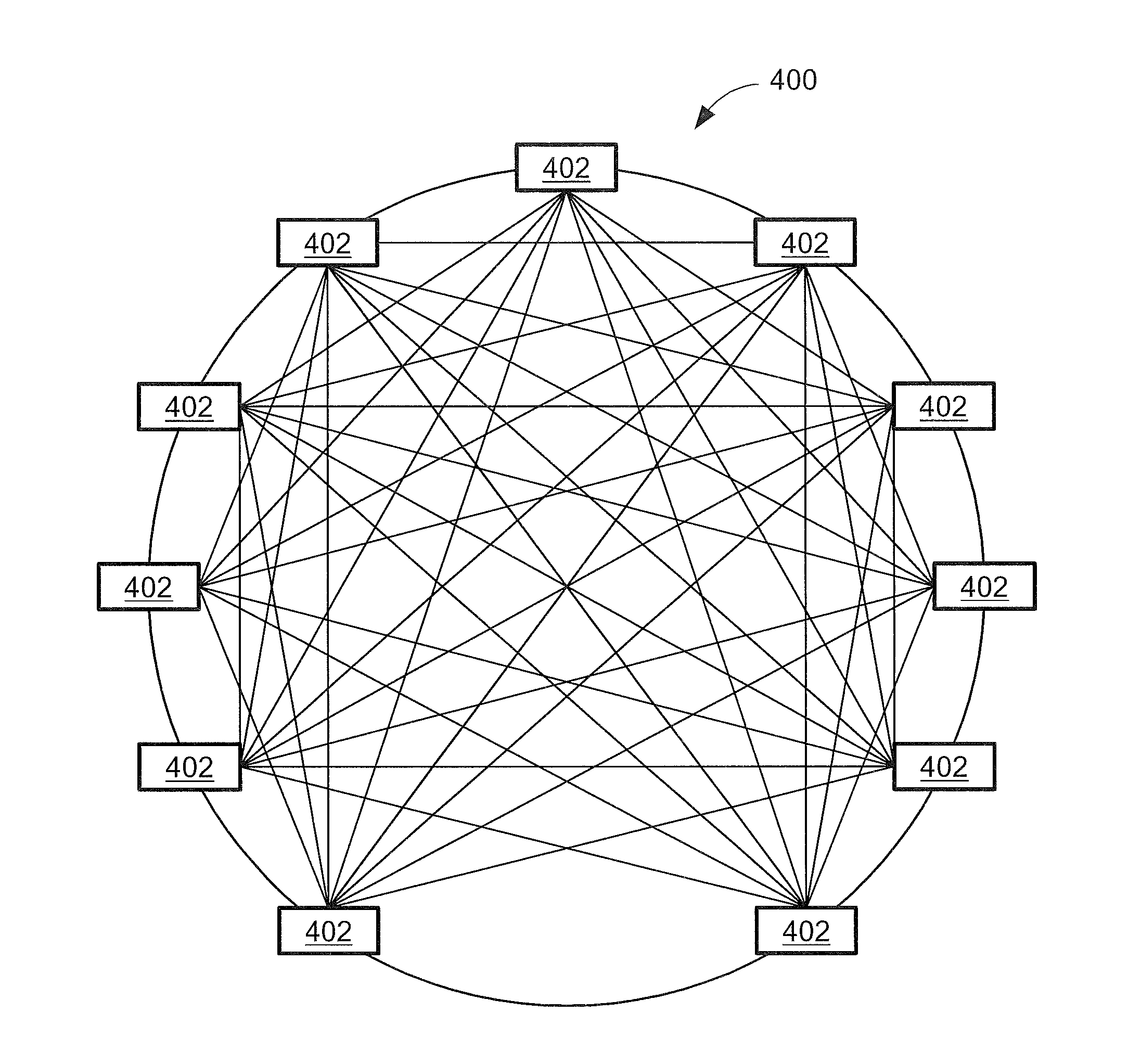
[0036]FIG. 4 shows a network 400 that is implemented in a meshed ring architecture, where each switch 402 has a direct connection with all of the other switches 402. In prior implementations of network 400, each connection was accomplished with one or more physical cables. Such a physical topology implementation is limited in terms of scalability, since the size is limited by the total number of switch ports available for interconnection for each switch through a physical cable.

[0037]FIG. 5 shows a network 500 organized as a three dimension flattened butterfly topology. This topology of network 500 can scale to large numbers of switch nodes 510 that can s...


PUM


Abstract

A system and method for connectivity configuration of a network node permits an optical signal to be passed through the node and shifted from a first connector position to a second connector position that is offset from the first connector position. The shifted optical signal permits a number of distant nodes in the network to be reached with a direct optical connection, which can be configured to be bidirectional. The disclosed connectivity configuration reduces the cabling requirements for the network and simplifies the interconnections.

Description

STATEMENT REGARDING FEDERALLY SPONSORED RESEARCH OR DEVELOPMENT[0001](Not Applicable)BACKGROUND OF THE INVENTION[0002]Communication networks tend to be constructed according to various physical and / or logical topologies, which can often depend on the capabilities of the components of the communication network. For example, FIG. 1 shows a communication network 100 in a hierarchical topology previously used in enterprise and data center communication networks.[0003]Network 100 has a lower layer 110 comprised of servers 112, which are typically rack mounted or otherwise concentrated with regard to physical location. A layer 120 uses layer 2 top-of-the rack (TOR) switches 122 to connect servers 112. A layer 130 is composed of layer 2 and / or layer 3 aggregation switches (AS) 132 to interconnect several TOR switches 122. A layer 140 is the top layer of network 100, and is composed of core routers (CR) 142 that connect aggregation switches 132. Often, core routers 142 also function as a ga...

Claims


Application Information

Patent Timeline
Patent Type & Authority Applications(United States)
IPC IPC(8): H04L12/24H04Q11/00
CPCH04L41/0806H04Q11/0005H04Q2011/0035H04L41/0893H04L41/12H04Q2011/0018
Inventor SPOCK, DEREK E.LI, RUODING
Owner HEWLETT-PACKARD ENTERPRISE DEV LP
Why Eureka
Try Eureka