
Cable tray splice and support

Inactive Publication Date: 2015-03-19
WINN RICHARD GREGG
View PDF19 Cites 16 Cited by
  • Summary
  • Abstract
  • Description
  • Claims
  • Application Information

AI Technical Summary

Benefits of technology

This patent is about a system for installing electrical system conductors. It uses special rods to connect wire cable trays together. The rods are designed to be strong and rigid, reducing stress concentration points and providing better overall stability. The system also includes a support system for the wire cable trays, ensuring proper installation and stability during use.

Problems solved by technology

Such fractures can be easily caused by high stress point loads on an optical cable when the optical cable is resting on the wire rods of a standard cable tray.
Such pressure points can fracture the optical fibers, but the sensitivity of optical fibers is such that even excessive pressure on the optical fibers themselves can affect many of the key performance characteristics of the optical cable such as the optical fiber's transmission signal speed, the operable bandwidth of the optical fiber, and the general performance integrity of the optical cable.
In severe cases, these excessive pressures can also affect these same performance characteristics for copper data cables.

Method used


Image

  • Cable tray splice and support
  • Cable tray splice and support
  • Cable tray splice and support

Examples


Embodiment Construction

[0024]In the following description, numerous specific details are set forth such as examples of specific components, devices, methods, in order to provide a thorough understanding of embodiments of the present disclosure. It will be apparent to a person of ordinary skill in the art that these specific details need not be employed, and should not be construed to limit the scope of the disclosure. In the development of any actual implementation, numerous implementation-specific decisions must be made to achieve the developer's specific goals, such as compliance with system-related and business-related constraints. Such a development effort might be complex and time consuming, but is nevertheless a routine undertaking of design, fabrication, and manufacture for those of ordinary skill.

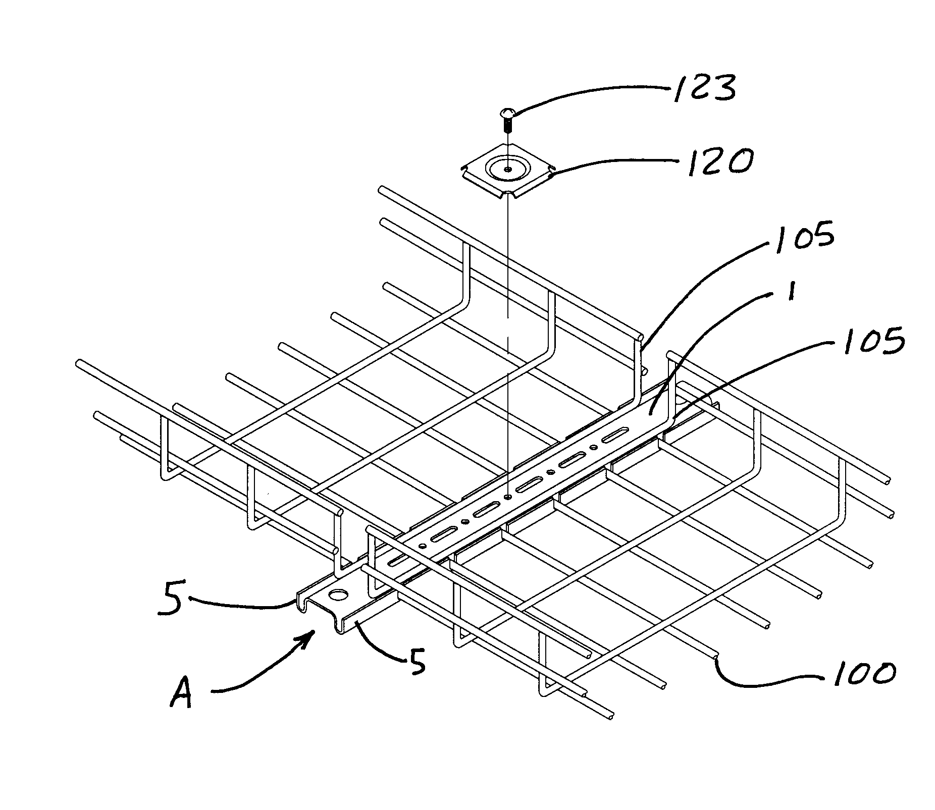
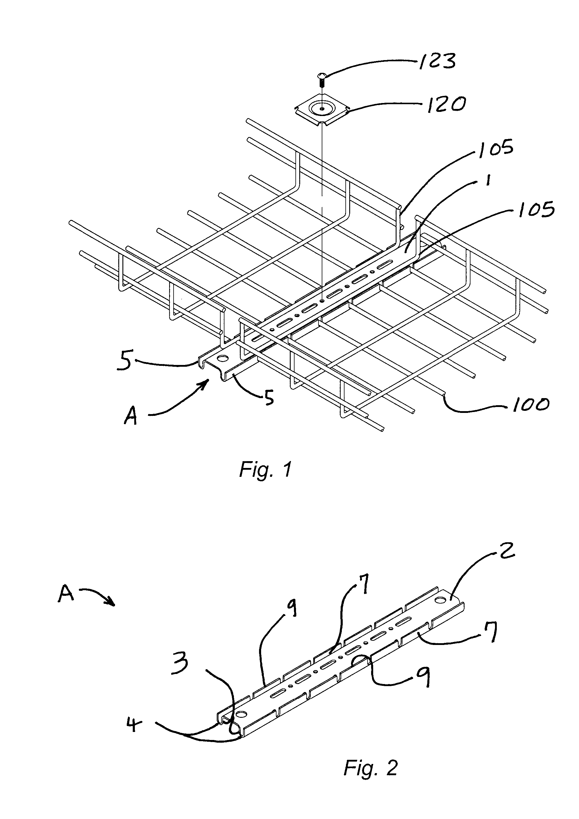
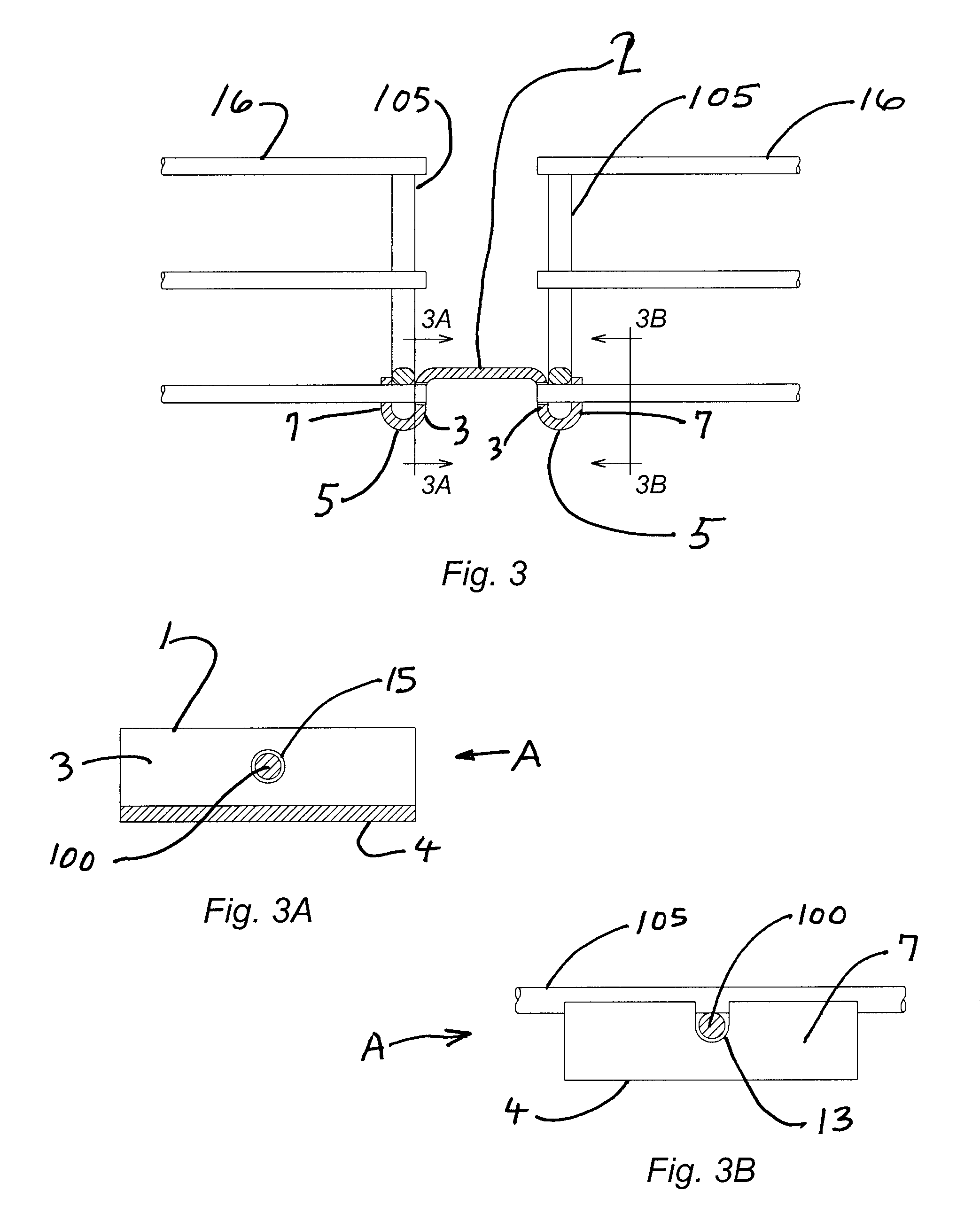
[0025]A set of preferred embodiments of the CABLE TRAY SPLICE AND SUPPORT A of the present invention are illustrated in FIG. 1 through FIG. 9. One example of the physical configuration of a preferred embo...


PUM


Abstract

A wire cable tray splice and support device that can be used splice to wire cable trays together to generate a substantially continuous series of wire cable trays. Various embodiments of the present invention can splice wire cable trays together that the ends of two wire cable trays, or can be used to support a set of wire cable trays from a structure above the wire cable trays, or can be used o mount a series of wire cable trays together along the surface of a vertical wall.

Description

CROSS REFERENCE TO RELATED APPLICATIONS[0001]This application claims all benefits from U.S. Provisional Application Ser. No. 61 / 878,002 filed Sep. 15, 2013 which is incorporated by reference as if fully stated herein, and as necessary to support the embodiments and claims herein.STATEMENT REGARDING FEDERALLY SPONSORED RESEARCH[0002]Not Applicable.BACKGROUND OF THE INVENTION[0003]Electrical system conductors are part of the construction of virtually any building whether the building is residential, business, or even a storage building. In most applications, local construction codes and building techniques dictate the use of metallic conduit mounted to various surfaces of the building. The necessary electrical system conductors are then drawn through the metallic conduit to terminate at the various control points designed within the electrical system.[0004]With the widespread use of a virtually endless variety of electronic equipment and devices, there has also been a constant and ste...

Claims


Application Information

Patent Timeline
IPC IPC(8): H02G3/06
CPCH02G3/06H02G3/0443H02G3/0608
Inventor WINN, RICHARD GREGG
Owner WINN RICHARD GREGG
Features
  • Generate Ideas
  • Intellectual Property
  • Life Sciences
  • Materials
  • Tech Scout
  • Unparalleled Data Quality
  • Higher Quality Content
  • 60% Fewer Hallucinations
Learn More