
Adjustable Fixture for a Multi-Spindle Machine

a multi-spindle machine and adjustable fixture technology, applied in the field of manufacturing, can solve the problem that manufacturing aircraft may require large amounts of time and expens

Active Publication Date: 2015-03-19
THE BOEING CO
View PDF5 Cites 16 Cited by
  • Summary
  • Abstract
  • Description
  • Claims
  • Application Information

AI Technical Summary

Benefits of technology

The patent describes an apparatus and method for machining workpieces using a multi-spindle machine and an adjustment system. The apparatus includes a plurality of platforms that can hold workpieces and are individually moveable with respect to each other. The adjustment system can move each platform independently from the others. This allows for flexibility and efficiency in machining the workpieces. The method involves positioning tools and workpieces on the platforms, and then using the multi-spindle machine to perform the necessary operations. The resulting parts can be machined on both sides, and the process can be repeated with different adjustments for the workpieces. Overall, the apparatus and method provide a more efficient and flexible way to machine workpieces.

Problems solved by technology

Manufacturing aircraft may require large amounts of time and expense as compared to smaller or simpler objects or structures.

Method used


Image

  • Adjustable Fixture for a Multi-Spindle Machine
  • Adjustable Fixture for a Multi-Spindle Machine
  • Adjustable Fixture for a Multi-Spindle Machine

Examples


Embodiment Construction

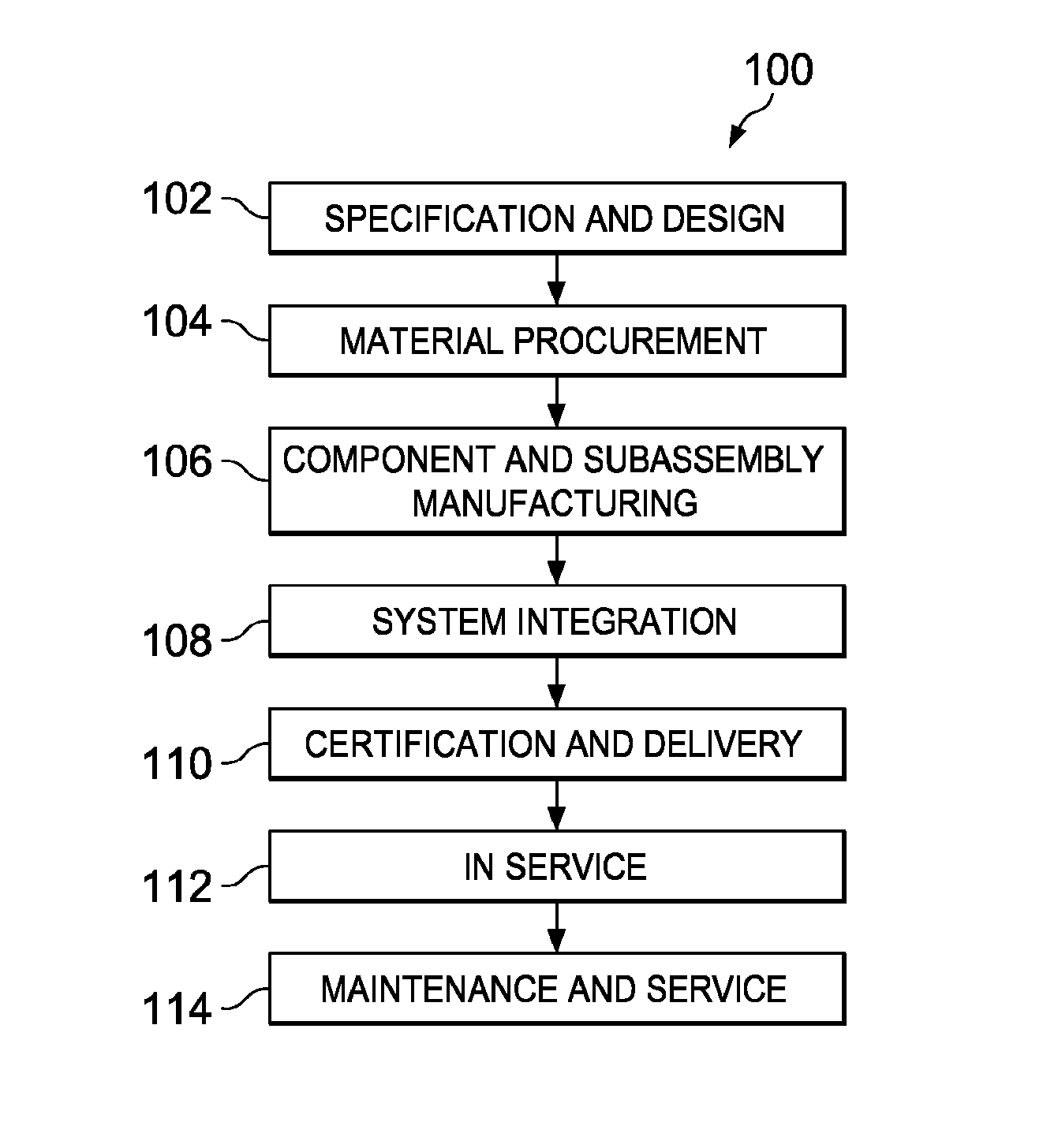
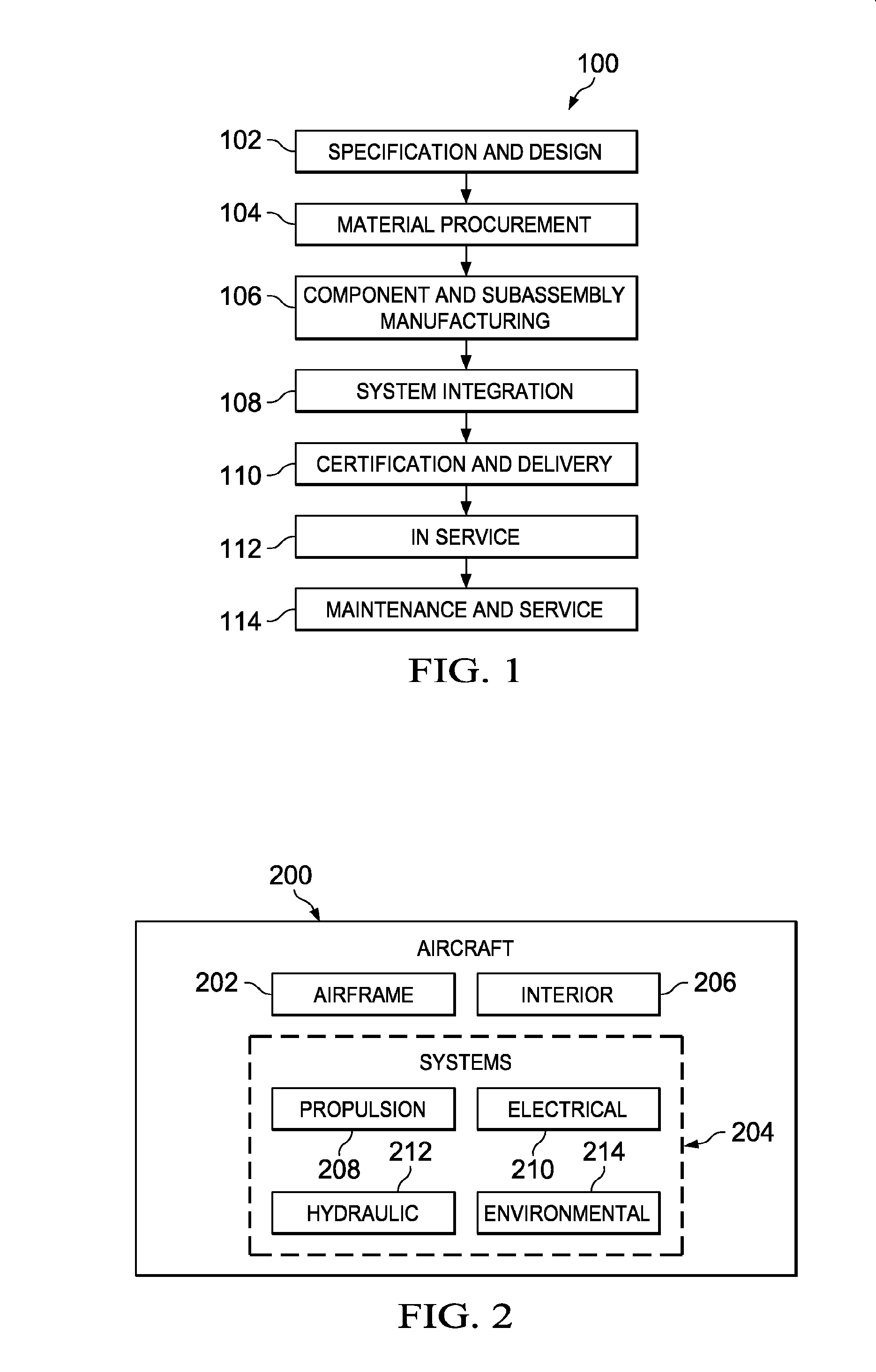
[0032]Referring more particularly to the drawings, embodiments of the disclosure may be described in the context of aircraft manufacturing and service method 100 as shown in FIG. 1 and aircraft 200 as shown in FIG. 2. Turning first to FIG. 1, an illustration of an aircraft manufacturing and service method is depicted in accordance with an advantageous embodiment. During pre-production, aircraft manufacturing and service method 100 may include specification and design 102 of aircraft 200 in FIG. 2 and material procurement 104.

[0033]During production, component and subassembly manufacturing 106 and system integration 108 of aircraft 200 in FIG. 2 may take place. Thereafter, aircraft 200 in FIG. 2 may go through certification and delivery 110 in order to be placed in service 112. While in service 112 by a customer, aircraft 200 in FIG. 2 is scheduled for routine maintenance and service 114, which may include modification, reconfiguration, refurbishment, and other maintenance or service...


PUM

PropertyMeasurementUnit
timeaaaaaaaaaa
shapeaaaaaaaaaa
dimensionsaaaaaaaaaa

Abstract

A method and apparatus for processing workpieces to form parts. Tools associated with a multi-spindle machine may be positioned with respect to a plurality of workpieces on a fixture comprising a plurality of platforms and an adjustment system. Each platform may be individually moveable with respect to others in the plurality of platforms about a number of axes. The plurality of platforms may be configured to hold the plurality of workpieces in which each platform may be configured to hold a workpiece in the plurality of workpieces during operations performed by the multi-spindle machine. The adjustment system may be configured to move each of the plurality of platforms about the number of axes independently from the others in the plurality of platforms. The operations may be performed on the plurality of workpieces using the multi-spindle machine and the fixture to form a plurality of parts.

Description

[0001]This application is a divisional application of U.S. application Ser. No. 12 / 623,756, filed Nov. 23, 2009.BACKGROUND INFORMATION[0002]1. Field[0003]The present disclosure relates generally to manufacturing and, in particular, to a method and apparatus for manufacturing parts using machines. Still more particularly, the present disclosure relates to a method and apparatus for machining workpieces with a multi-spindle machine to form parts.[0004]2. Background[0005]Manufacturing aircraft may require large amounts of time and expense as compared to smaller or simpler objects or structures. It may be desirable to reduce the amount of time needed to manufacture an aircraft. By reducing the amount of time needed to manufacture an aircraft, an aircraft manufacturer may deliver an aircraft to its customers earlier and receive revenues for those aircraft more quickly.[0006]In manufacturing aircraft, the time involved in manufacturing parts for the aircraft and / or assembling the parts to...

Claims


Application Information

Patent Timeline
Patent Type & Authority Applications(United States)
IPC IPC(8): B23B1/00B23Q1/26B23Q1/44B23C1/08
CPCB23B1/00B23Q1/44B23Q1/26B23C1/08B23Q3/061B23Q39/04B23Q2039/002Y10T408/3806Y10T409/308344Y10T408/3833Y10T409/307168Y10T408/385Y10T409/305264Y10T29/5107Y10T409/308288Y10T409/300112Y10T409/30112Y10T409/303752Y10T409/400175Y10T409/50082Y10T408/03Y10T29/49996B23P23/02B23Q1/46B23Q1/42B23C1/002B23B39/161B23B39/18B23B39/006B23Q2039/006B23Q7/165B23Q1/62
Inventor HANKS, RYAN L.WAYMACK, KEVIN G.HECK, DAVID P.
Owner THE BOEING CO
Learn More