Ultralow expansion glass

a technology of ultralow expansion and glass, applied in the field of ultralow expansion glass, can solve the problems of slow relaxation glass, inconvenient, expensive, time-consuming, etc., and achieve the effect of slow relaxation

Active Publication Date: 2015-03-19
CORNING INC
View PDF4 Cites 10 Cited by
  • Summary
  • Abstract
  • Description
  • Claims
  • Application Information

AI Technical Summary

Benefits of technology

[0010]The methods of the present disclosure may transform an initial glass article to a finished glass article. The glass article may include titania-silica glass. The titania-silica glass may have a titania content in the range from 5 wt % to 12 wt %, or in the range from 7 wt % to 12 wt %, or in the range from 6 wt % to 10 wt %, or in the range from 7.5 wt % to 9 wt %. Additionally, the titania-silica glass may typically include OH in the range from 700 ppm to 1000 ppm by weight, or in an amount of about 850 ppm. The present invention also applies to higher or lower OH-containing sil

Problems solved by technology

As the size of mirror substrates increases, the requirements for uniformity of Tzc and CTE slope will become increasingly stringent and more challenging to achieve.
Relying on compositional variations to mee

Method used


Image

  • Ultralow expansion glass
  • Ultralow expansion glass
  • Ultralow expansion glass

Examples


example 1

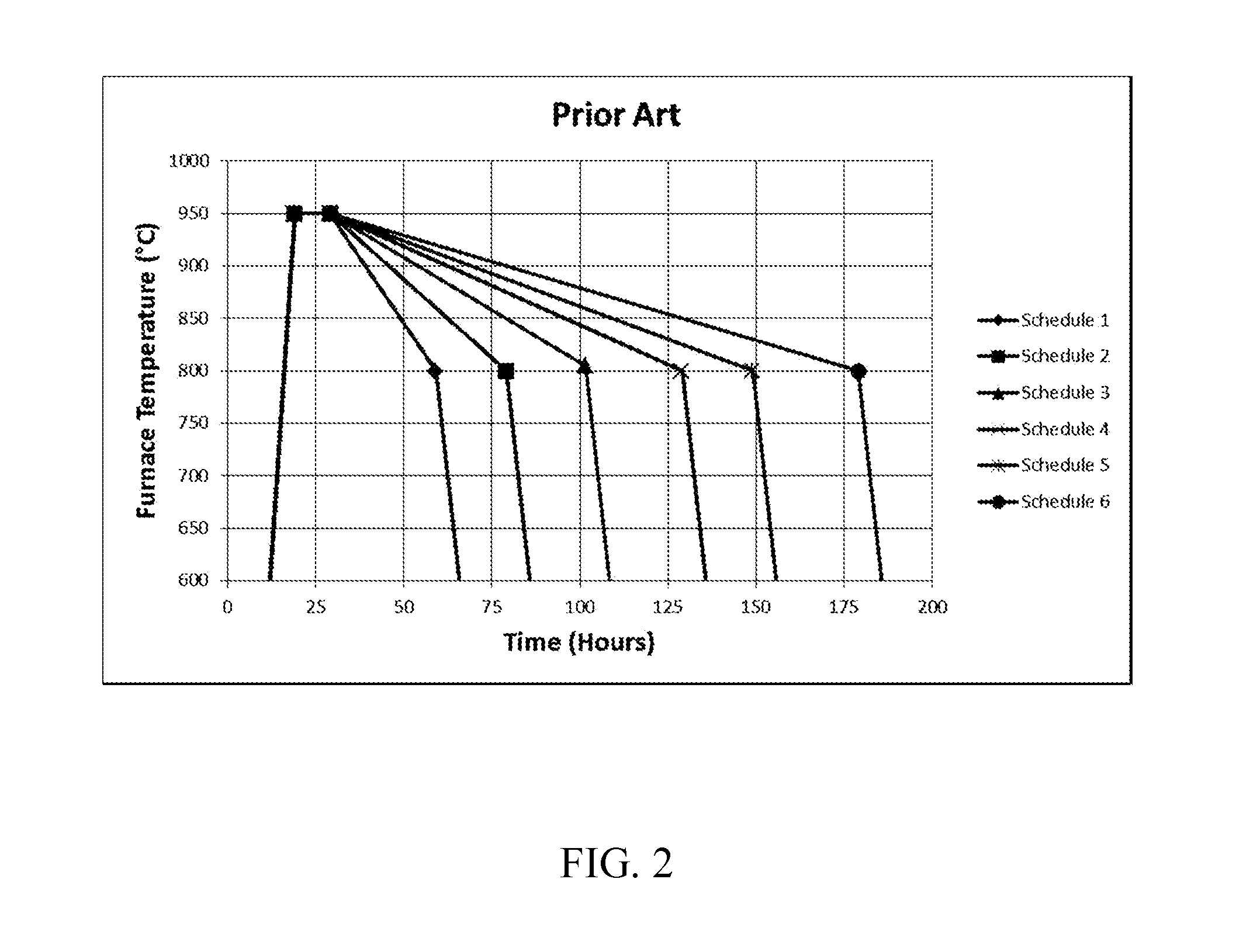
[0122]FIG. 6 illustrates representative annealing schedules in accordance with the present disclosure. Six annealing schedules are depicted. Each annealing schedule includes heating to an elevated temperature of 950° C. and holding at 950° C. for several hours. Annealing schedules 1-3 include a common rate of cooling from 950° C. to an intermediate temperature of 825° C. and differ in the rate of cooling from 825° C. to an annealing endpoint temperature of 700° C. Annealing schedules 4-6 include a common rate of cooling from 950° C. to an intermediate temperature of 825° C. and differ in the rate of cooling from 825° C. to an annealing endpoint temperature of 700° C. The rate of cooling between 950° C. and 825° C. differs for annealing schedules 1-3 and annealing schedules 4-6. The cooling rate below 700° C. to room temperature is the same for annealing schedules 1-6.

[0123]Although not explicitly shown, several additional annealing schedules of the type shown in FIG. 6 were devised ...

example 2

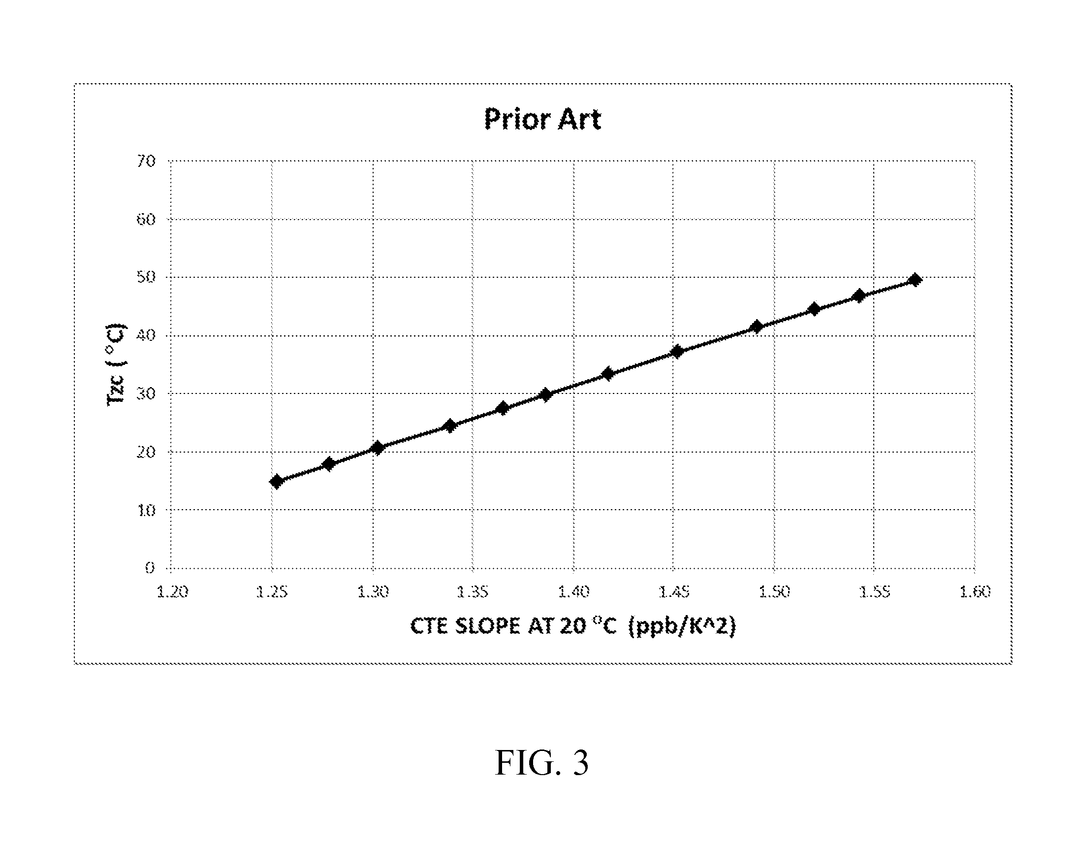
[0130]FIG. 8 shows alternative annealing schedules that permit independent control of Tzc and CTE slope. Six representative annealing schedules are shown. Each annealing schedule includes heating to an elevated temperature of 950° C. and holding at 950° C. for several hours. Annealing schedules 1-3 include a common rate of cooling from 950° C. to different intermediate temperatures (˜860° C., ˜825° C., and ˜780° C.) followed by cooling at a common faster rate to room temperature. Annealing schedules 4-6 include a common rate of cooling (different from the rate of cooling used for annealing schedules 1-3) from 950° C. to different intermediate temperatures (˜855° C., ˜815° C., and ˜770° C.) followed by cooling at a common faster rate (the same faster rate as used in annealing schedules 1-3) to room temperature.

[0131]The common rate of cooling from the elevated temperature for annealing schedules 1-3 shown in FIG. 8 is expected to establish a common fictive temperature and a common CT...


PUM

PropertyMeasurementUnit
Temperatureaaaaaaaaaa

Abstract

Silica-titania glasses with small temperature variations in coefficient of thermal expansion over a wide range of zero-crossover temperatures and methods for making the glasses. The method includes a cooling protocol with controlled anneals over two different temperature regimes. A higher temperature controlled anneal may occur over a temperature interval from 750° C.-950° C. or a sub-interval thereof. A lower temperature controlled anneal may occur over a temperature interval from 650° C.-875° C. or a sub-interval thereof. The controlled anneals permit independent control over CTE slope and Tzc of silica-titania glasses. The independent control provides CTE slope and Tzc values for silica-titania glasses of fixed composition over ranges heretofore possible only through variations in composition.

Description

[0001]This application claims the benefit of priority under 35 U.S.C. §119 of U.S. Provisional Application Ser. No. 61 / 877,422 filed on Sep. 13, 2013 the content of which is relied upon and incorporated herein by reference in its entirety.FIELD OF THE DISCLOSURE[0002]This disclosure pertains to a glass having ultralow thermal expansion. More particularly, this disclosure relates to silica-titania glasses having a small variation in coefficient of thermal expansion over a temperature range around the zero crossover temperature. Most particularly, this disclosure relates to annealing methods that permit independent control of the temperature slope and the zero crossover temperature of the coefficient of thermal expansion of silica-titania glasses and to silica-titania glasses formed by the methods.BACKGROUND OF THE DISCLOSURE[0003]Mirror substrates used in projection optics systems of extreme ultraviolet lithography (EUVL) scanners must meet stringent thermal expansion requirements in...

Claims


Application Information

Patent Timeline
IPC IPC(8): C03B25/02C03C3/06
CPCC03B25/02C03C2201/00C03C3/06C03B25/00C03B25/08C03B2201/42C03C3/076C03C2201/42Y02P40/57
Inventor DURAN, CARLOS ALBERTO
Owner CORNING INC
Why Eureka
Try Eureka