Synchronized array of vibration actuators in a network topology

a technology of vibration actuators and network topology, which is applied in the direction of adaptive control, computer control, instruments, etc., can solve the problems of high rate of vibration change, inability to provide more of a sensation in the forward direction relative to the backward direction or vice versa, and inability to define the directionality of the vibratory for

Active Publication Date: 2015-03-19
COACTIVE DRIVE CORP
View PDF4 Cites 94 Cited by
  • Summary
  • Abstract
  • Description
  • Claims
  • Application Information

AI Technical Summary

Benefits of technology

[0009]It is desirable to produce not only haptic directional cues but also to be able to render legacy haptic effects, so that a single game controller could generate both new and existing sensations. Therefore, one aspect of this disclosure and associated embodiments described in this specification include vibration devices and methods of operating those devices employing multiple, low-cost actuator components in lieu of a single, high-cost actuator for creating haptic effects. The aspects described within this disclosure include synchronizing arrays of low-cost, readily available vibration actuators to emulate superlative single actuators and to bring together sets of these emulated high-performance actuators to create a broad range of desired control effects.

Problems solved by technology

A common limitation of most existing vibration devices is the inability to define the directionality of the vibratory forces.
ERM actuators generate centripetal forces that rotate in a plane, and generally the direction of vibration (that is to say, the instantaneous direction of the rotating centripetal force vector) cannot be not sensed in haptic applications due in part to the high rate of change of the direction of vibrations.
LRAs vibrate back and forth, and thus it may be possible to sense the axis of vibration, but it is not possible to provide more of a sensation in the forward direction relative to the backward direction or vice versa.
There have been some haptic vibration devices that provide a sensation of vibration direction, but these prior implementations have disadvantages.
However, existing asymmetric vibrators are complex, costly, or have limited controllability.
They tend to be bulky and have low power efficiency.
Tappeiner et. al. demonstrated a vibration device that generated asymmetric directional haptic cues (Tappeiner, H. W.; Klatzky, R. L.; Unger, B.; Hollis, R., “Good vibrations: Asymmetric vibrations for directional haptic cues”, World Haptics 2009, Third Joint Euro Haptics Conference and Symposium on Haptic Interfaces for Virtual Environments and Teleoperator Systems), yet this device uses a high power and an expensive 6-DOF magnetic levitation haptic device.
403-414”) illustrated a device that also generates asymmetric vibrations for haptic applications, yet this device uses a complex and large linkage system with 6 links and it appears that the direction of vibration cannot be modified in real-time.
Another limitation of vibration devices that use ERMs is that the amplitude of vibration is dependent on the frequency of vibration, since the vibration forces are generated from centripetal acceleration of an eccentric mass.
Some prior approaches have used multiple ERMs to control frequency and amplitude independently, but in the process also generate undesirable torque effects due to the offset between the ERMs.

Method used


Image

  • Synchronized array of vibration actuators in a network topology
  • Synchronized array of vibration actuators in a network topology
  • Synchronized array of vibration actuators in a network topology

Examples


embodiment 600

[0276]An embodiment 600 of the present disclosure with a haptic interface application is shown in FIG. 37. In this embodiment a systems controller 602 provides force commands to a haptic interface 604 which generates forces which result in force sensations to user 606. The systems controller 602 may be microprocessor, a central processing unit, an ASIC, a DSP, a game controller, an analog controller, or other type of controller or any combination thereof. The user 606 can input commands to the haptic interface 604 that are transmitted as user commands back to the system controller 602. The user commands can be input through pressing buttons, moving joysticks, squeezing the haptic interface at various level forces, moving the haptic interface, applying force and torque onto the haptic interface and through other means.

[0277]In the embodiment shown in FIG. 37, there is preferably a graphical display 608 which receives an image command from the system controller 602 and displays a visu...

embodiment 620

[0279]Another embodiment 620 having a haptic interface application is shown in FIG. 38. This embodiment is similar to the one of FIG. 37, and includes a systems controller 622, which provides force commands to a haptic interface 624 that generates forces which result in force sensations being received by user 626. A graphical display 628 is also provided for receiving image commands from the system controller 622 and for displaying a visual image to the user 626.

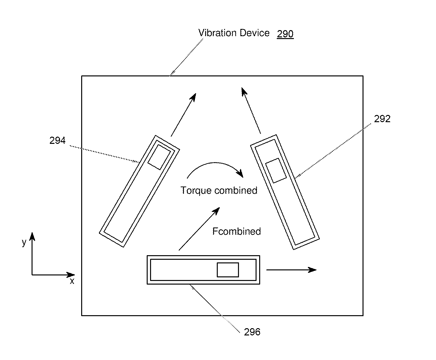
[0280]In the embodiment of FIG. 38, the haptic interface 624 desirably includes a vibration device 630 having vibration actuators (not shown), a vibration controller 632, driver circuits 634 which drive the vibration device actuators, and an input device 636, which can detect user input and which can include buttons, joysticks, and pressure sensors. The components of the haptic interface 624 may be of any of the configurations described herein. In this embodiment the graphical display 628 preferably presents a two dimensiona...

embodiment 710

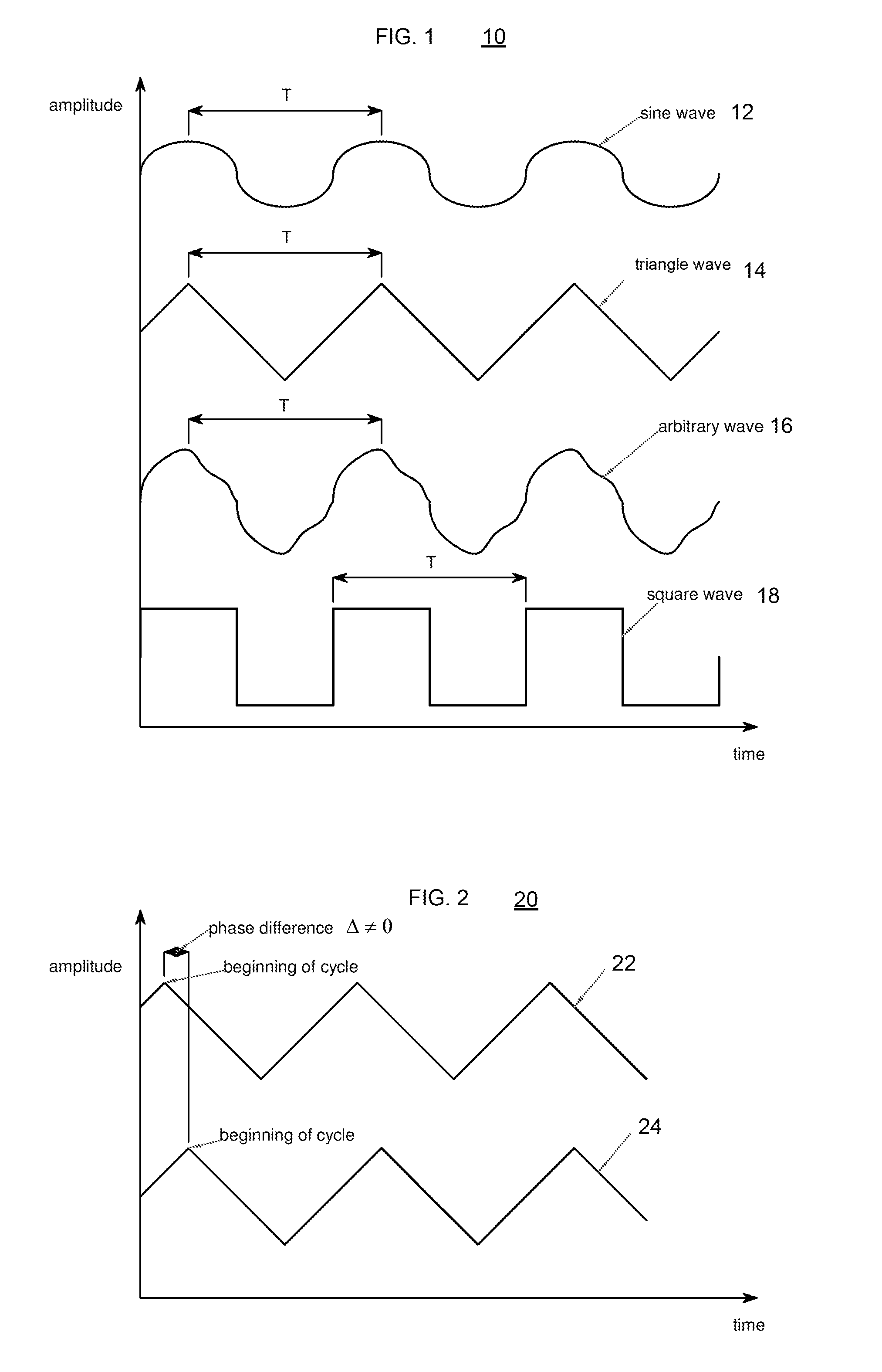
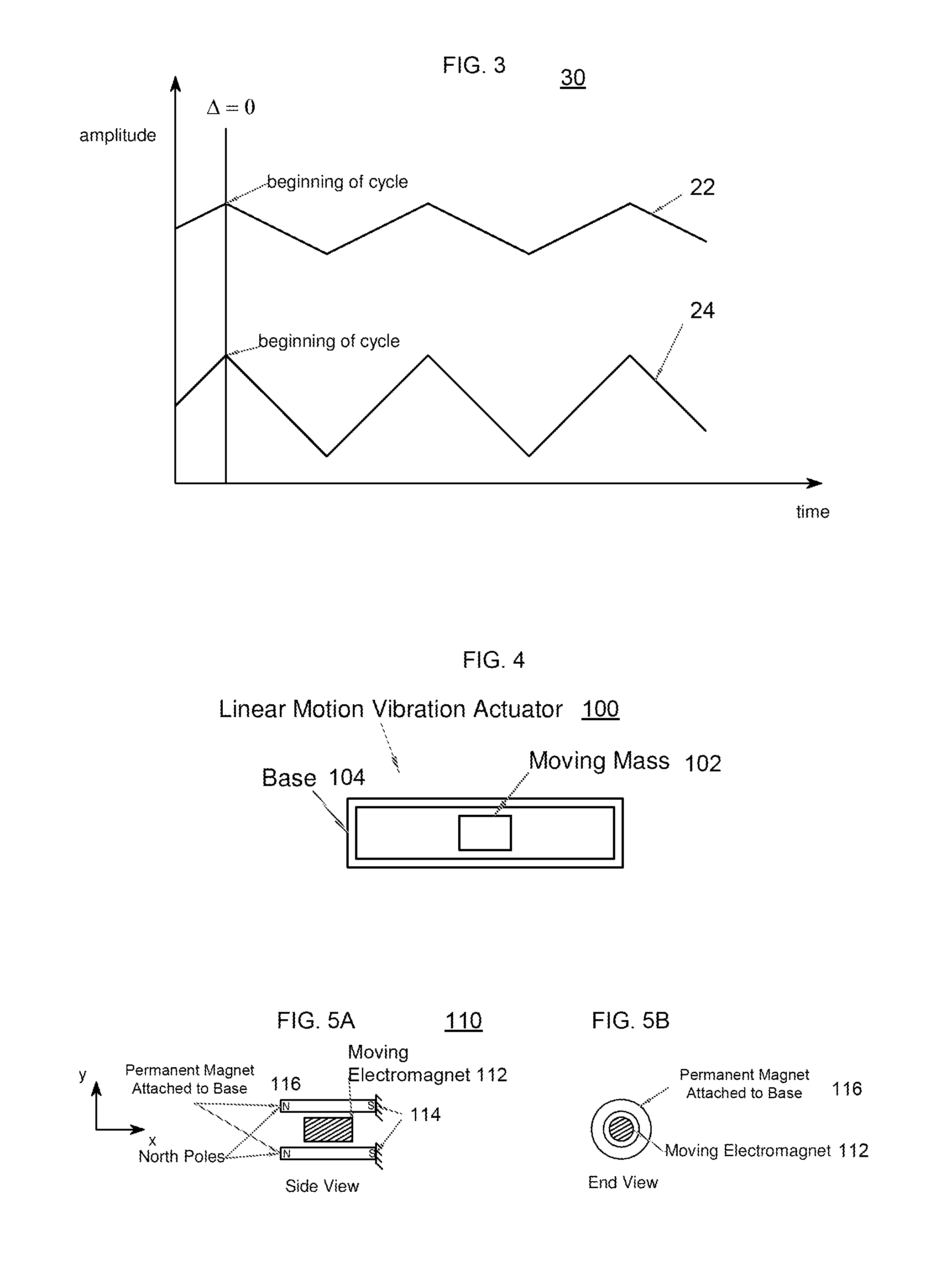
[0311]To further simplify the vibration controller circuitry and lower cost, the amplitude of the vibration signal can be modulated with a PWM signal, where the duty cycle of the signal is proportional to the amplitude of vibration. An embodiment 710 with such a digital vibration controller 712 for one actuator 716 is shown in FIG. 41. In this embodiment, the output of the digital vibration controller 712 includes an amplitude signal in PWM form and a direction signal, for instance in the form of a logic bit, both of which preferably are sent to a driver circuit 714. The driver circuit 714, in turn, sends electrical power to the actuator 716.

[0312]Digital control circuitry can be used to control a complete vibration device in synchronized vibration. In synchronized vibration the frequency and phase of two or more actuators are the same. Accordingly, a single square wave can be used to control the direction of the vibration actuators that are in synchronized vibration. The amplitude ...


PUM


Abstract

The disclosure relates to a Synchronized Array of Vibration Actuators in a Network Topology providing synchronized arrays of low-cost, readily available vibration actuators to emulate superlative single actuators and bring together sets of these emulated high-performance actuators to create a broad range of desired control effects. Such actuator arrays may operate in both spatial and temporal modes, creating haptic effects that relate to the user via their position and orientation in space. The spatial mode may create h-pulses or the amplitude of a vibrational effect may change based on position of the device. The temporal mode may create vibrational effects that interact with the user to create an awareness of time. Additionally modes include performance, bandwidth, magnitude and reliability modes. The different control modalities may be combined together into a single vector control space, which spans the haptic capabilities of sets and / or subsets of actuators.

Description

CROSS REFERENCE TO RELATED APPLICATIONS[0001]This application claims the benefit of the filing date of U.S. Provisional Patent Application No. 61 / 607,092, filed Mar. 6, 2012 and entitled SYNCHRONIZED ARRAY OF VIBRATION ACTUATORS IN A NETWORK TOPOLOGY, the entire disclosure of which is hereby expressly incorporated by reference herein. This application is also a continuation-in-part of U.S. patent application Ser. No. 13 / 422,453, filed Mar. 16, 2012 and entitled ASYMMETRIC AND GENERAL VIBRATION WAVEFORMS FROM MULTIPLE SYNCHRONIZED VIBRATION ACTUATORS, which is a continuation-in-part of U.S. patent application Ser. No. 13 / 030,663, filed Feb. 18, 2011, and entitled SYNCHRONIZED VIBRATION DEVICE FOR HAPTIC FEEDBACK, which is a continuation of U.S. application Ser. No. 11 / 476,436, filed Jun. 27, 2006, issued on Apr. 5, 2011 as U.S. Pat. No. 7,919,945, which claims the benefit of the filing date of U.S. Provisional Patent Application No. 60 / 694,468 filed Jun. 27, 2005 and entitled SYNCHRO...

Claims


Application Information

Patent Timeline
Patent Type & Authority Applications(United States)
IPC IPC(8): G05D19/02
CPCG05D19/02
Inventor HOUSTON, JOHNMORRIS, ROBDELSON, NATHANGRAHAM, GABE
Owner COACTIVE DRIVE CORP
Why Eureka
Try Eureka