
Independent flow rate controlling hydraulic system for pressure control of excavator and independent hydraulic pressure controlling method using the same

a flow rate control and hydraulic system technology, applied in the direction of fluid couplings, rotary clutches, servomotors, etc., can solve the problems of inconvenience for operators, inability to efficiently correspond to changes in the environment in which they are used, and limited degree of freedom of the system for hydraulic control

Inactive Publication Date: 2015-03-26
HYUNDAI HEAVY IND CO LTD
View PDF1 Cites 3 Cited by
  • Summary
  • Abstract
  • Description
  • Claims
  • Application Information

AI Technical Summary

Benefits of technology

The present invention is about improving the control of multiple actuators in heavy construction equipment, such as an excavator, using electronic proportional control valves. These valves allow for independent control of each actuator based on the operator's manipulation of the control stick, resulting in greater flexibility in flow rate control. This can improve fuel efficiency and minimize operator inconvenience. The valves are placed on both the inlet and outlet sides of the actuators, allowing for efficient operation. Additionally, the pressure control-type hydraulic pump ensures that no unwanted flow is discharged when the control stick is in a neutral position. Overall, this invention realizes a closed-center system and allows for precise control of flow rates.

Problems solved by technology

Therefore, in some aspects, they fail to efficiently correspond to changes in the environment in which they are used, such as a load size, a direction, a possibility of the use of gravitational energy, or the like.
Depending on the behaviors and preferences of individual operators in operating excavators, an excavator's operability in response to changes is limited, thereby causing inconvenience for the operator.
In addition, the degree of freedom of the system for hydraulic control is limited, thereby making it difficult to improve energy efficiency.

Method used

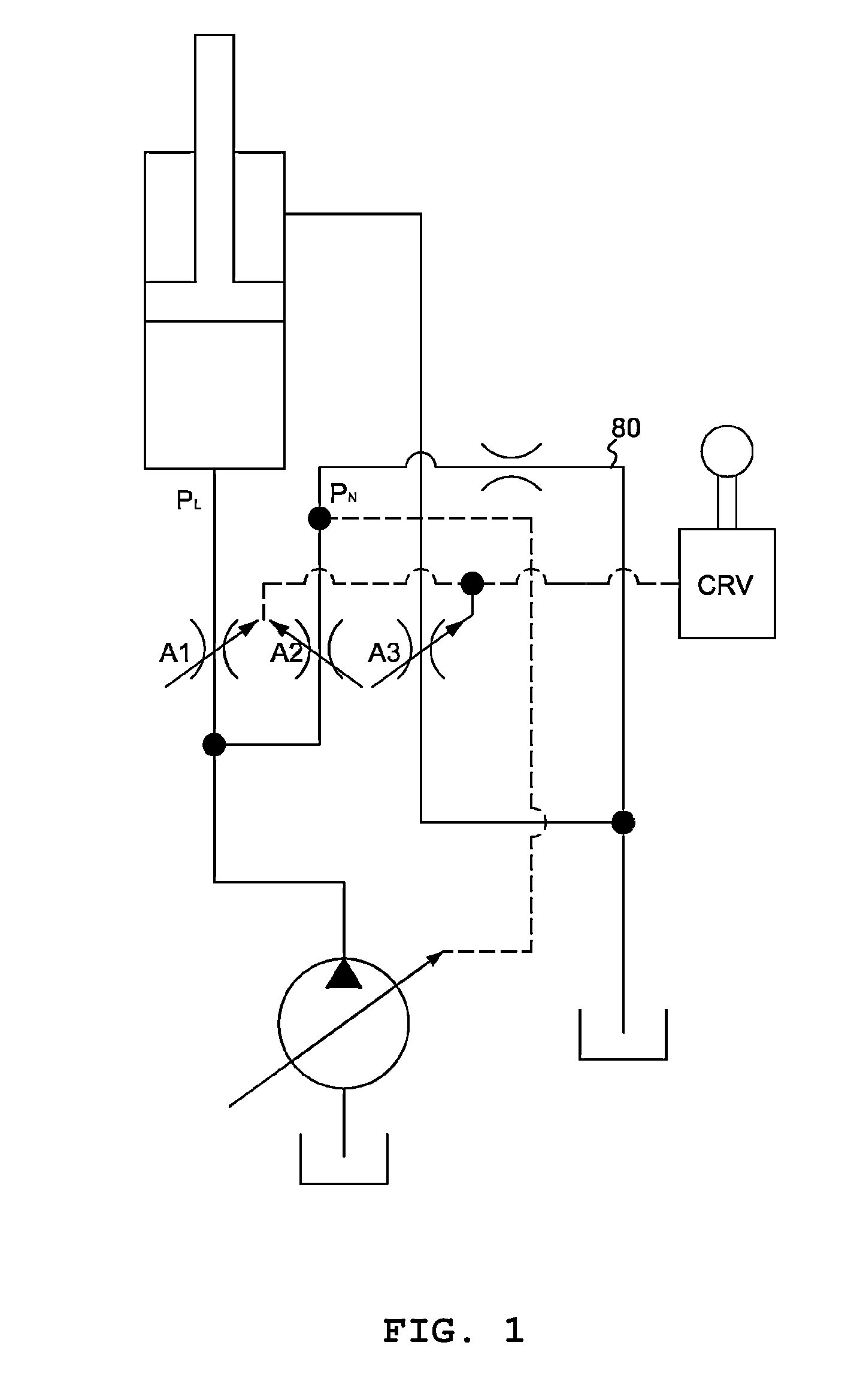
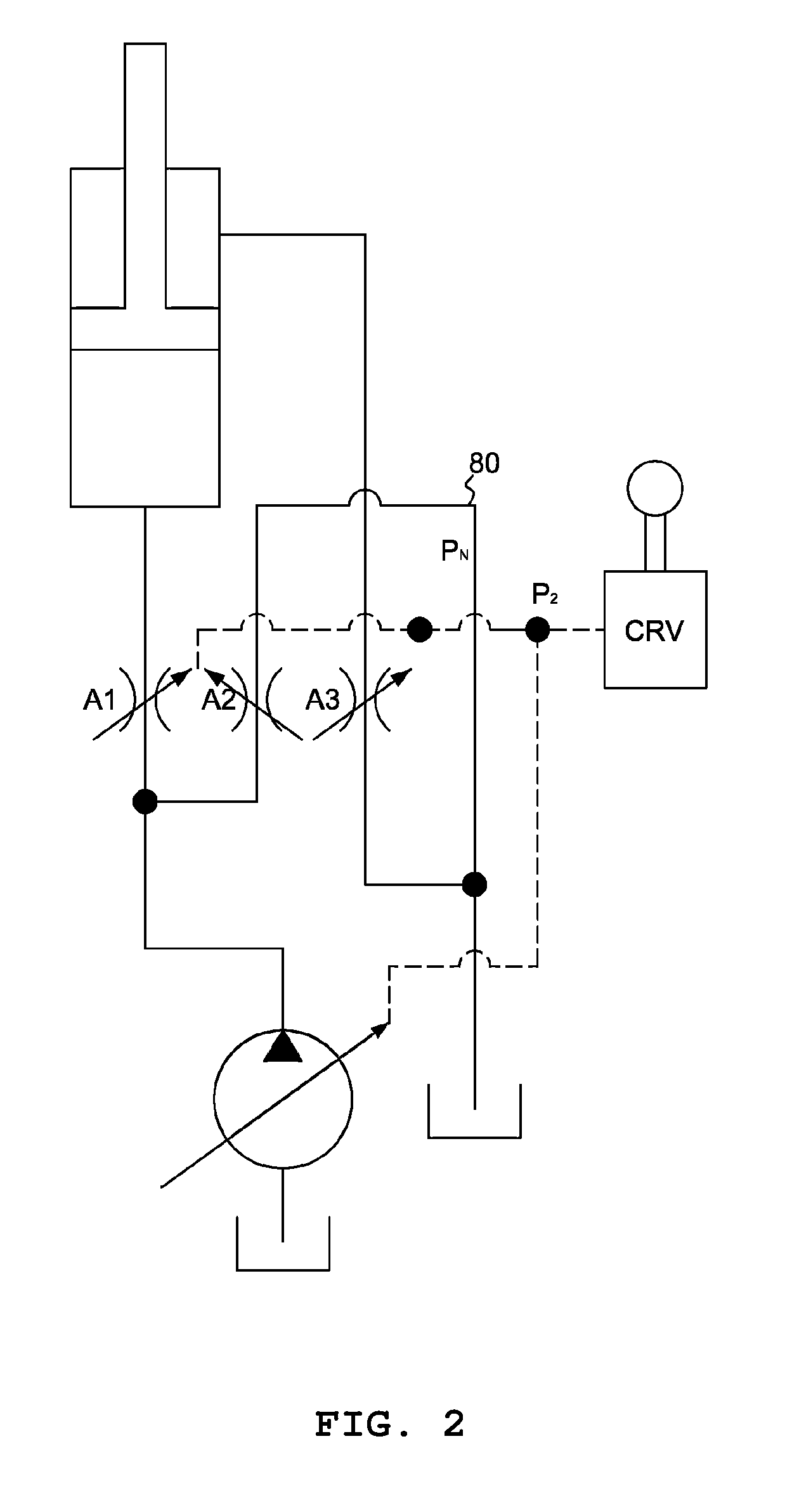

Image

  • Independent flow rate controlling hydraulic system for pressure control of excavator and independent hydraulic pressure controlling method using the same
  • Independent flow rate controlling hydraulic system for pressure control of excavator and independent hydraulic pressure controlling method using the same
  • Independent flow rate controlling hydraulic system for pressure control of excavator and independent hydraulic pressure controlling method using the same

Examples


Embodiment Construction

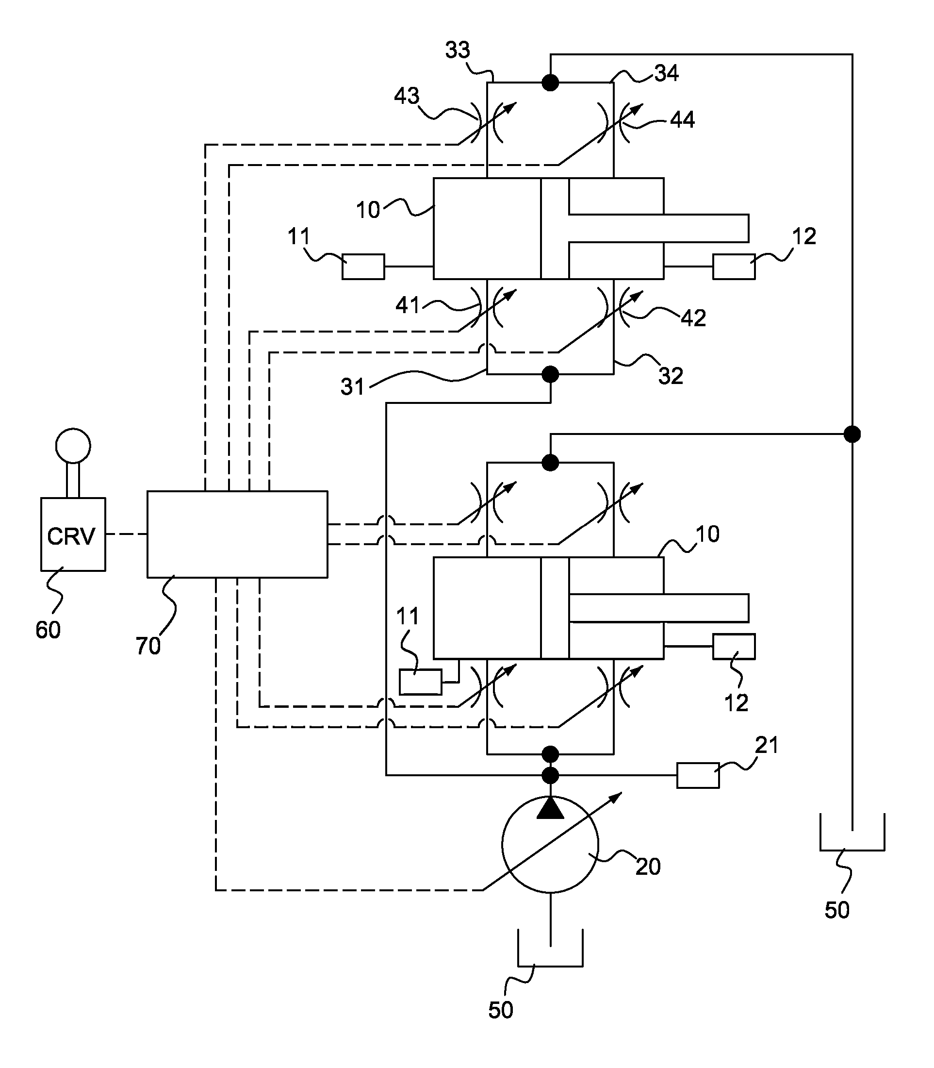
[0030]An independent flow rate controlling hydraulic system (an independent metering system) for pressure control of an excavator variably controls the areas of flow paths with electronic proportional control valves respectively disposed along all flow paths in order to significantly increase the degree of freedom in flow rate control. As major characteristics, the independent flow rate controlling hydraulic system has a pressure control-type hydraulic pump disposed therein, and is embodied as a closed-center system.

[0031]FIG. 4 is an example view showing the configuration of the present invention. The present invention includes a plurality of actuators 10 which actuate a working apparatus, a pressure control-type hydraulic pump 20 which feeds working fluid to the actuators 10, first and second electronic proportional control valves 41 and 42 which are disposed at a piston-side inlet flow path 31 and a load-side inlet flow path 32 connected from the hydraulic pump 20 to the actuator...


PUM


Abstract

An independent flow rate controlling hydraulic system for pressure control of an excavator, in which a hydraulic system of the excavator can be variably controlled via independent flow rate control. The hydraulic system includes a plurality of actuators which actuate a working apparatus, a pressure control-type hydraulic pump which feeds working fluid to the actuator, first and second electronic proportional control valves which are disposed at a piston-side inlet flow path and a load-side inlet flow path connected from the hydraulic pump to the actuators, third and fourth electronic proportional control valves which are disposed at a piston-side outlet flow path and a load-side outlet flow path connected from the actuators to a hydraulic tank, and a control unit which variably controls areas of the flow paths by controlling the first, second, third and fourth electronic proportional control valves depending on an amount by which a control stick is manipulated.

Description

CROSS-REFERENCE TO RELATED APPLICATIONS[0001]This is a Continuation-in-part Application of PCT / KR2013 / 004585, filed on May 27, 2013, which designates the United States and claims the benefit of priority from Korean Patent Application No. 10-2012-0056687, filed on May 29, 2012, the disclosures of both of which are expressly incorporated by reference herein in their entireties.TECHNICAL FIELD[0002]The present invention relates to an independent flow rate controlling hydraulic system for pressure control of an excavator and an independent hydraulic pressure controlling system using the same, and more particularly, to an independent flow rate controlling hydraulic system for pressure control of an excavator in which the areas of flow paths are variably controlled using electronic proportional control valves which are disposed on each flow path that is necessary for the control over an actuator, whereby the degree of freedom of the flow control is significantly increased, and an independ...

Claims


Application Information

Patent Timeline
IPC IPC(8): F15B11/16E02F9/22
CPCF15B11/162E02F9/2278F15B2211/513F15B2211/413F15B2211/3144E02F3/435E02F9/2228E02F9/2296F15B11/006F15B2211/20546F15B2211/30575F15B2211/327F15B2211/351F15B2211/353F15B2211/6346F15B2211/665F15B2211/6652F15B2211/6654E02F9/22F15B13/044
Inventor CHOI, LIM-GOOKSHIN, DONG-BINPARK, TAE-SUNGLEE, JONG-CHAN
Owner HYUNDAI HEAVY IND CO LTD
Learn More