Reduced Reaction Rotary Alternating Current Generator

Inactive Publication Date: 2015-03-26
PARAMAHAMSA TEWARI
View PDF3 Cites 3 Cited by
  • Summary
  • Abstract
  • Description
  • Claims
  • Application Information

AI Technical Summary

Benefits of technology

The present invention is a new kind of generator that solves problems with older generators. It is designed to improve efficiency and is better than standard generators. This is its main purpose.

Problems solved by technology

The efficiency of an electrical generator is governed by mechanical and electrical limitations.
The mechanical limitations include windage and friction of the generator's rotor and bearings.
The electrical limitations include electrical impedance within the windings of the generator as well as the above-described counter or back torque.
Therefore, the problem with standard generators is that their efficiency is limited due to back torque generated as a result of current induced within the generator's conductor windings.

Method used


Image

  • Reduced Reaction Rotary Alternating Current Generator
  • Reduced Reaction Rotary Alternating Current Generator
  • Reduced Reaction Rotary Alternating Current Generator

Examples


Embodiment Construction

[0024]The present invention relates to a reduced reaction rotating alternating current generator providing improvement in efficiency characteristics not currently available in standard alternating current generators.

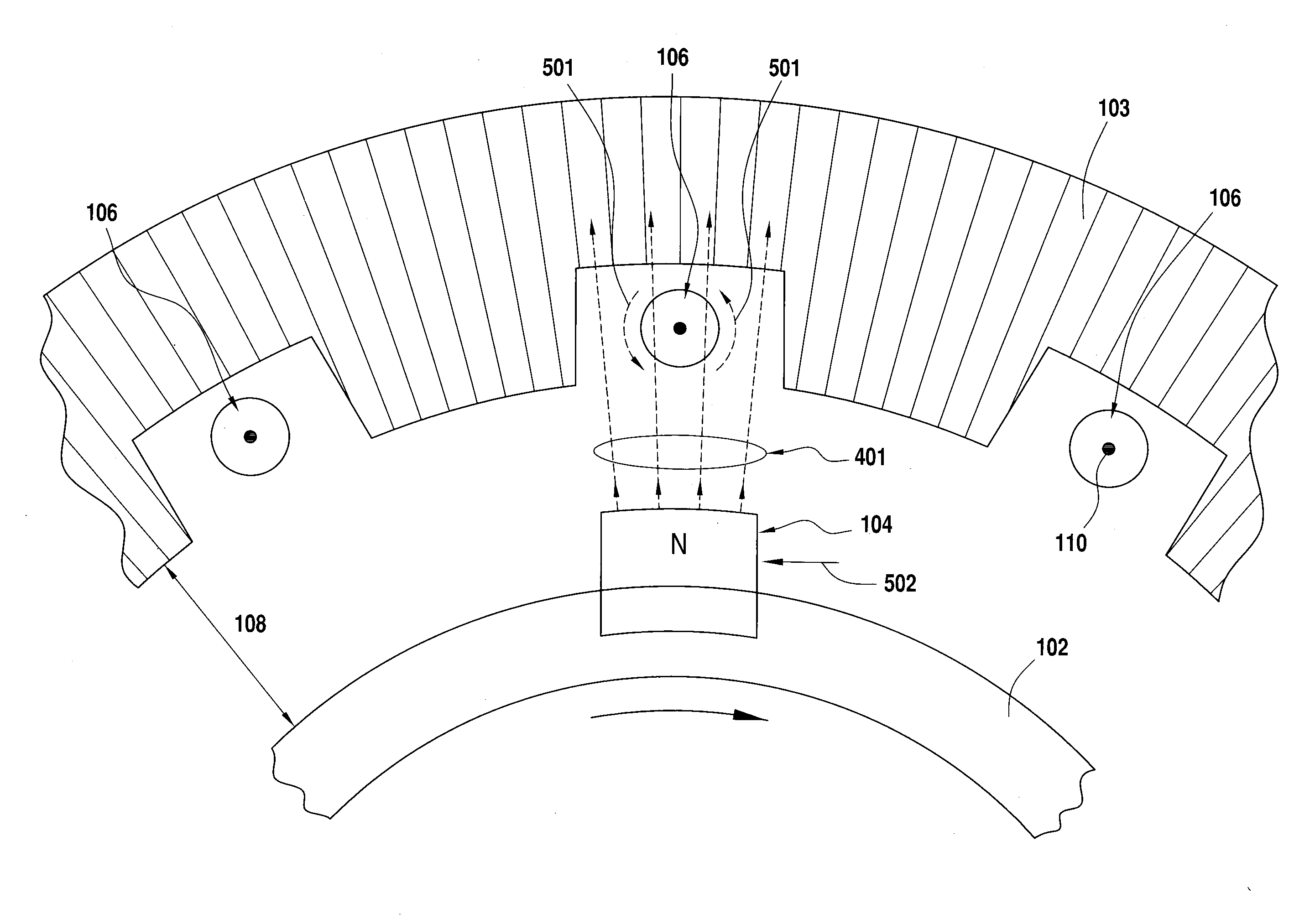
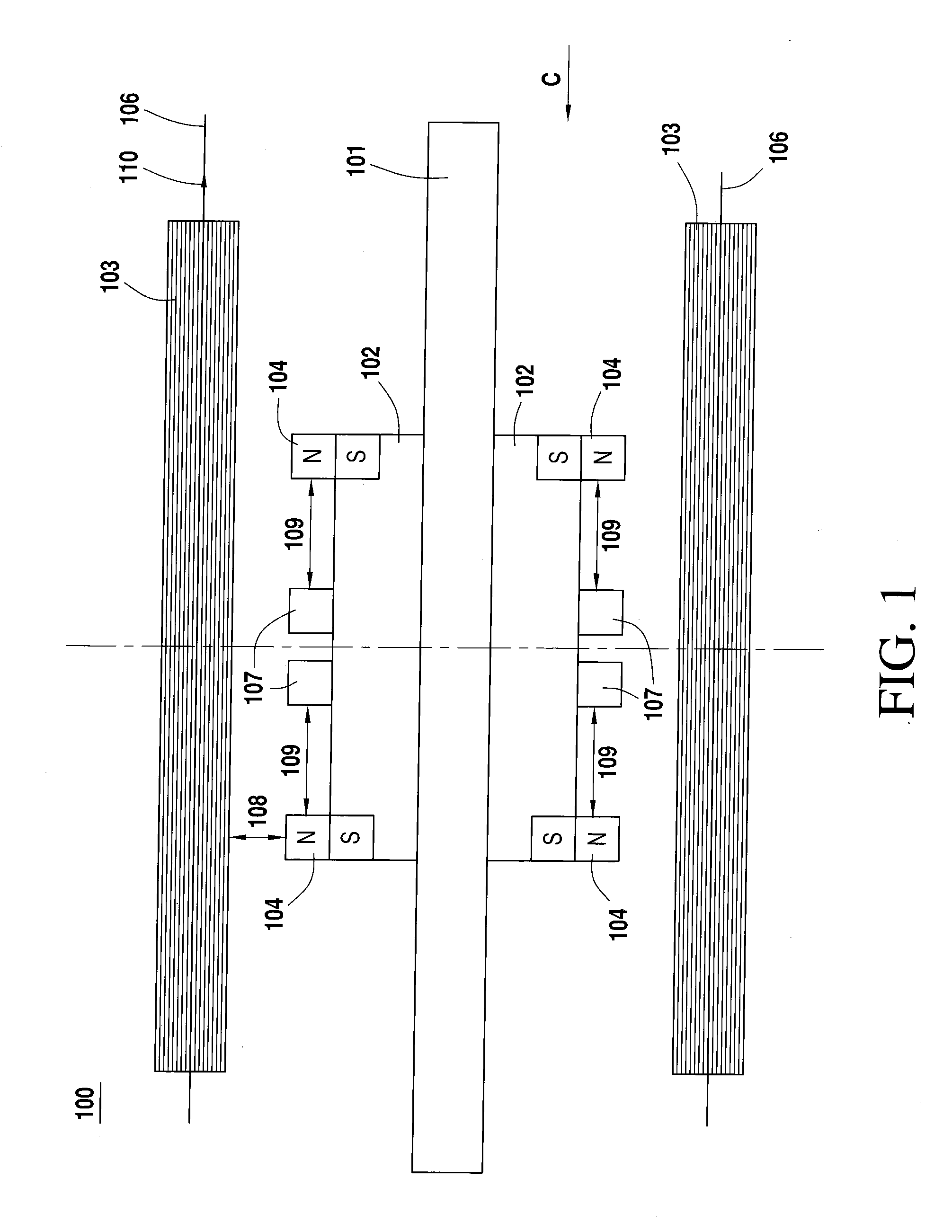
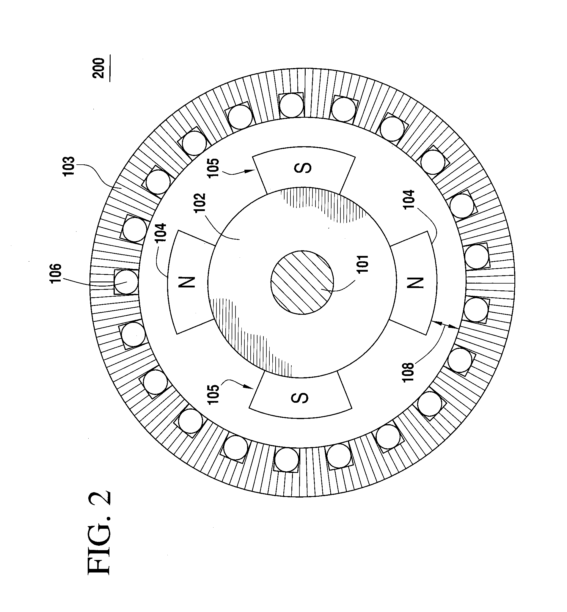
[0025]FIG. 1 depicts a longitudinal cross sectional view of a reduced reaction alternating current generator according to an exemplary embodiment of the present invention. As shown by FIG. 1, the induction machine 100 comprises a shaft 101, a rotor 102, a stator 103, a first set of magnets 104, a second set of magnets 105 (not shown), a conductor winding 106 and silicon steel pieces 107.

[0026]The rotor 102 is a cylinder of high permeability magnetic material attached directly to the shaft 101 using any conventional known method that provides for a secure and permanent bonding under normal operating conditions. The rotor 102 is sized to be fully encompassed within the stator 103 while the shaft 101 is sized to extend beyond at least one end of the stator 103.

[0027]The sha...


PUM


Abstract

A reduced reaction alternating current generator including a hollow stator core, a cylindrical rotor within the stator, a freely rotating shaft coupled to the rotor, a first set of magnets in which the south pole of each magnet is coupled to the surface to the rotor and the north pole of each magnet is facing the inner surface of the hollow stator core, a second set of magnets in which the north pole of each magnet is coupled to the surface of the rotor and the south pole of each magnet is facing the inner surface of the hollow stator core and a set of silicon steel pieces coupled to the outer surface of the rotor comprised of individual silicon steel pieces positioned adjacent to and longitudinally in line with each individual magnet within the first set of magnets and each individual magnet within the second set of magnets.

Description

RELATED APPLICATION[0001]This application claims the benefit of U.S. provisional patent application No. 61 / 960,752, filed Sep. 26, 2013, in the name of Paramahamsa Tewari, the disclosure of which is incorporated herein by reference.FIELD OF THE INVENTION[0002]The present invention relates to a rotating alternating current generator whose structural characteristic provide for a reduction in the amount force running counter to the rotation of the machine as a reaction to the induced alternating current.BACKGROUND OF THE INVENTION[0003]Michael Faraday discovered the principles of electromagnetic induction and invented the rotating electrical generator in 1832. The generator was known as the Unipolar Generator, Acyclic Generator and Disk Generator. This generator operated on the principle that voltage is induced in a conductor in relative motion to an external magnetic field. Moreover, when the conductor is configured as a closed circuit and is in relative motion with an external magnet...

Claims


Application Information

Patent Timeline
IPC IPC(8): H02K1/27
CPCH02K1/272H02K21/14
Inventor PARAMAHAMSA, TEWARI
Owner PARAMAHAMSA TEWARI
Why Eureka
Try Eureka