Method Of Manufacturing Thin-Film Bonded Substrate Used For Semiconductor Device

Inactive Publication Date: 2013-12-05
SAMSUNG CORNING PRECISION MATERIALS CO LTD
View PDF4 Cites 3 Cited by
  • Summary
  • Abstract
  • Description
  • Claims
  • Application Information

AI Technical Summary

Benefits of technology

The present invention provides a method for manufacturing a thin-film bonded substrate used for semiconductor devices without using a conductive barrier layer and preventing malfunctions caused by high-temperature processing. Additionally, the method prevents cracks caused by the difference in coefficients of thermal expansion between heterogeneous materials. The process of forming an epitaxial growth layer on one surface of a bulk crystal before bonding it to a heterogeneous substrate reduces reaction between the materials and precludes a barrier layer. The use of reflective materials based on common inexpensive metals reduces manufacturing costs. Furthermore, the method simplifies the fabrication process for vertical LEDs compared to the related art.

Problems solved by technology

While GaN substrates are suitable for semiconductor devices together with gallium arsenide (GaAs) substrates, indium phosphide (InP) substrates, and the like, the manufacturing cost thereof is much more expensive than those of GaAs substrates and InP substrates.
Accordingly, the manufacturing cost of semiconductor devices which adopt GaN substrates becomes very high.
However, when the thickness of a GaN film to be cleaved from the GaN crystalline bulk is reduced in order to increase the number of cleaved GaN substrates, the mechanical strength of the cleaved substrates decreases to the extent that the cleaved substrates cannot create a self-supporting substrate.
However, GaN is decomposed into Ga and N at 1000° C., leading to the precipitation of Ga metal.
In addition, since the coefficient of thermal expansion of GaN is twice that of Si, the GaN / Si bonded substrate which is directly bonded at 200° C. is vulnerable to cracks due to the difference in the coefficients of thermal expansion while being cooled down to room temperature after epitaxial growth processing.
This requires the use of an expensive material in order to satisfy that requirement, thereby causing the problem of the increased manufacturing cost.

Method used


Image

  • Method Of Manufacturing Thin-Film Bonded Substrate Used For Semiconductor Device
  • Method Of Manufacturing Thin-Film Bonded Substrate Used For Semiconductor Device
  • Method Of Manufacturing Thin-Film Bonded Substrate Used For Semiconductor Device

Examples


Embodiment Construction

[0035]Reference will now be made in detail to a method of manufacturing a thin-film bonded substrate used for semiconductor devices according to the present invention, embodiments of which are illustrated in the accompanying drawings and described below, so that a person having ordinary skill in the art to which the present invention relates can easily put the present invention into practice.

[0036]Throughout this document, reference should be made to the drawings, in which the same reference numerals and signs are used throughout the different drawings to designate the same or similar components. In the following description of the present invention, detailed descriptions of known functions and components incorporated herein will be omitted when they may make the subject matter of the present invention unclear.

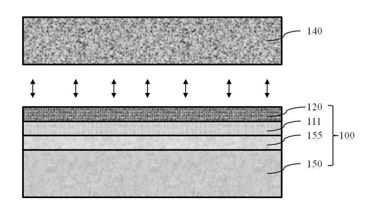
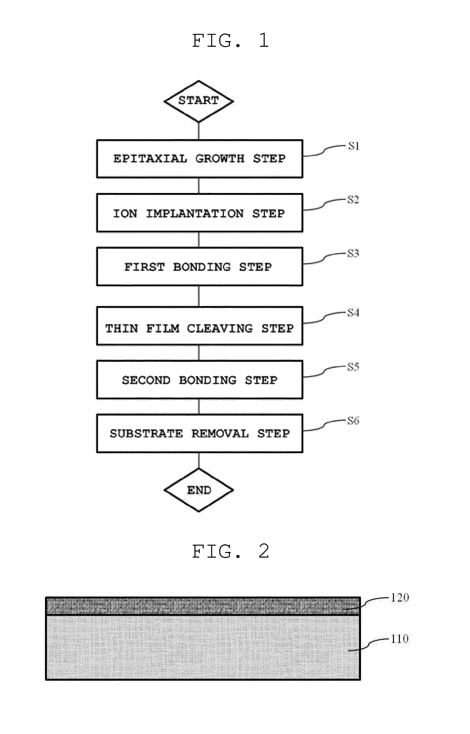
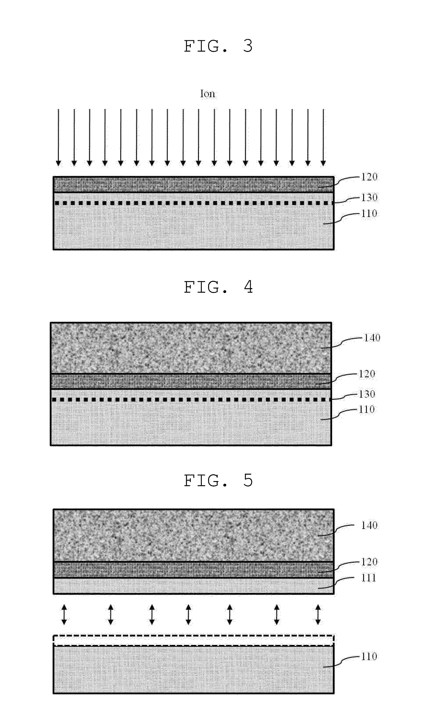
[0037]As shown in FIG. 1, the method of manufacturing a thin-film bonded substrate used for semiconductor devices includes an epitaxial growth step S1, an ion implantation ste...


PUM


Abstract

A method of manufacturing a thin-film bonded substrate used for semiconductor devices. The method includes the steps of epitaxially growing an epitaxial growth layer on a first substrate of a bulk crystal, cleaving the first substrate, thereby leaving a crystal thin film on the epitaxial growth layer, the crystal thin film being separated out of the first substrate, and bonding a second substrate to the crystal thin film, the chemical composition of the second substrate being different from the chemical composition of the first substrate. It is possible to preclude a conductive barrier layer of the related art, prevent a reflective layer from malfunctioning due to high-temperature processing, and essentially prevent cracks due to the difference in the coefficients of thermal expansion between heterogeneous materials that are bonded to each other.

Description

CROSS REFERENCE TO RELATED APPLICATION[0001]The present application claims priority from Korean Patent Application Number 10-2012-0056459 filed on May 29, 2012, the entire contents of which application are incorporated herein for all purposes by this reference.BACKGROUND OF THE INVENTION[0002]1. Field of the Invention[0003]The present invention relates to a method of manufacturing a thin-film bonded substrate used for semiconductor devices, and more particularly, to a method of manufacturing a thin-film bonded substrate used for semiconductor devices, which can preclude a conductive barrier layer of the related art, prevent a reflective layer from malfunctioning due to high-temperature processing, and essentially prevent cracks due to the difference in the coefficients of thermal expansion between heterogeneous materials that are bonded to each other.[0004]2. Description of Related Art[0005]The performance and lifespan of a semiconductor device, such as a laser diode or a light-emit...

Claims


Application Information

Patent Timeline
IPC IPC(8): H01L21/02
CPCH01L21/02694H01L33/46H01L33/62H01L2924/0002H01L33/0093H01L2924/00
Inventor KIM, DONGHYUNKIM, DONG-WOONKIM, MIKYOUNGKIM, MINJUKIM, A-RAKIM, HYUNJOONSHUR, JOONG WONWOO, KWANG-JELEE, BOHYUNJEON, JONGPILJUNG, KYUNGSUB
Owner SAMSUNG CORNING PRECISION MATERIALS CO LTD
Why Eureka
Try Eureka