Liquid ejecting apparatus

a liquid ejecting and apparatus technology, applied in the direction of typewriters, printing, inking apparatus, etc., can solve the problems of increasing the flow rate inside the internal flow path, the ejection performance of liquids is reduced, and the pressure loss is increased, so as to increase the resistance of the flow path of the second recovery path.

Active Publication Date: 2015-03-26
SEIKO EPSON CORP
View PDF11 Cites 9 Cited by
  • Summary
  • Abstract
  • Description
  • Claims
  • Application Information

AI Technical Summary

Benefits of technology

[0014]Furthermore, in an apparatus with which the liquid circulation part has a supply path configured to supply the liquid to the first head and the second head from the retaining part, it would be possible for the supply path to be constituted of a first branching point configured to branch the liquid being supplied to the first head from the liquid being supplied from the retaining part, a first supply path part configured to cause the liquid to flow to the first branching point, and a second supply path part configured to cause the liquid that was not branched at the first branching point to flow from the first branching point. In such a case, a change in the flow rate of the liq

Problems solved by technology

In particular, the recovery side (also called the return side) is majorly impacted by the pressure fluctuations, and this leads to a decrease in the ejection performance of the liquid.
Therefore, at every instance of passage through the second branch

Method used


Image

  • Liquid ejecting apparatus
  • Liquid ejecting apparatus
  • Liquid ejecting apparatus

Examples


Embodiment Construction

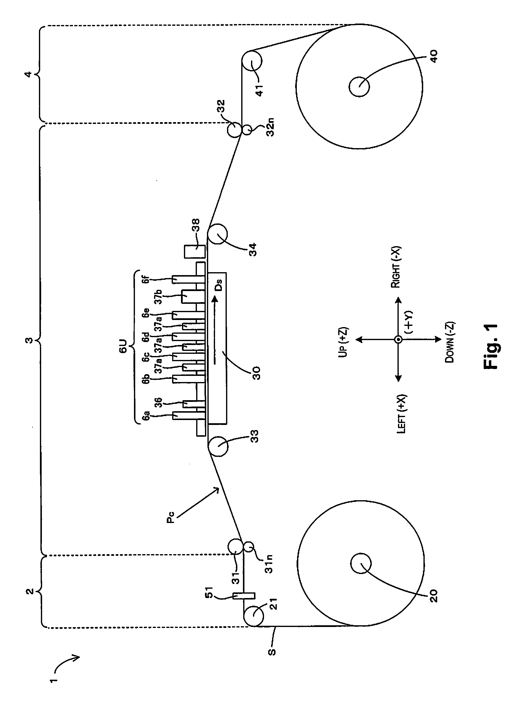
[0023]FIG. 1 is a front view schematically illustrating the configuration of a printer to which the present invention can be applied. In FIG. 1 and subsequent drawings, in order to clarify the relationships of arrangement among the respective parts of a printer 1, a three-dimensional coordinate system corresponding to a left-right direction X, front-rear direction Y, and vertical direction Z of the printer 1 shall be employed.

[0024]As illustrated in FIG. 1, the printer 1 has a feed-out part 2, a process part 3, and a take-up part 4 that are arrayed in the left-right direction. The feed-out part 2 and the take-up part4 include a feed-out spindle 20 and a take-up spindle 40, respectively. Two ends of a sheet S (medium) are wound in the form of a roll around the feed-out part 2 and the take-up part 4, the sheet S being stretched therebetween. The sheet S is conveyed to the process part 3 from the feed-out spindle 20 along a path of conveyance Pc on which the sheet S is thus stretched, ...


PUM


Abstract

A liquid circulation part has a recovery path where a liquid flows into a retaining part from a first head and a second head. The recovery path has a first merging point where the liquid flowing from the first head and the liquid flowing from the second head are merged, a first recovery path part where the liquid flowing from the first head flows into the first merging point, and a second recovery path part where the liquid flows from the first merging point. The cross-sectional area of the second recovery path part, orthogonal to a direction of flow of the liquid in the second recovery path part, is greater than the cross-sectional area of the first recovery path part, orthogonal to the direction of flow of the liquid in the first recovery path part.

Description

CROSS-REFERENCE TO RELATED APPLICATIONS[0001]This application claims priority to Japanese Patent Application No. 2013-194740 filed on Sep. 20, 2013. The entire disclosure of Japanese Patent Application No. 2013-194740 is hereby incorporated herein by reference.BACKGROUND[0002]1. Technical Field[0003]The present invention relates to a liquid ejecting apparatus provided with a plurality of heads for ejecting a liquid, and, in particular, to a technique for circulating a liquid through a plurality of heads.[0004]2. Related Art[0005]One known example of this type of liquid ejecting apparatus is an inkjet recording apparatus disclosed in Japanese laid-open patent publication 2011-79169. With this apparatus, ink supplied from an ink tank is distributed with an ink supply manifold. More specifically, the ink is distributed and supplied to respective head modules via a first branching flow path extending from the ink supply manifold. In turn, ink that is discharged from each of the head mod...

Claims


Application Information

Patent Timeline
IPC IPC(8): B41J2/185
CPCB41J2/185B41J2/175B41J2/18B41J29/38B41J3/543B41J2202/12B41J2202/20
Inventor ANDO, MASAAKIKOIKE, KAORU
Owner SEIKO EPSON CORP
Why Eureka
Try Eureka