Remote beam shaping

a beam shaping and remote technology, applied in the field of lighting, can solve the problem of too uniform light field, and achieve the effect of small cross-section

Inactive Publication Date: 2015-03-26
KONINKLIJKE PHILIPS ELECTRONICS NV +1
View PDF12 Cites 2 Cited by
  • Summary
  • Abstract
  • Description
  • Claims
  • Application Information

AI Technical Summary

Benefits of technology

[0003]In some cases, the uniformly directional light field may have a relatively small cross-section, for example such as the beam of light em

Problems solved by technology

However, in some circumstances in such applications, such a light field may be too un

Method used


Image

  • Remote beam shaping
  • Remote beam shaping
  • Remote beam shaping

Examples


Embodiment Construction

[0059]The present invention will now be described more fully hereinafter with reference to the accompanying drawings, in which exemplifying embodiments of the present invention are shown. The present invention may, however, be embodied in many different forms and should not be construed as limited to the embodiments set forth herein; rather, these embodiments are provided by way of example so that this disclosure will convey the scope of the invention to those skilled in the art. Furthermore, like numbers refer to like or similar elements or components throughout.

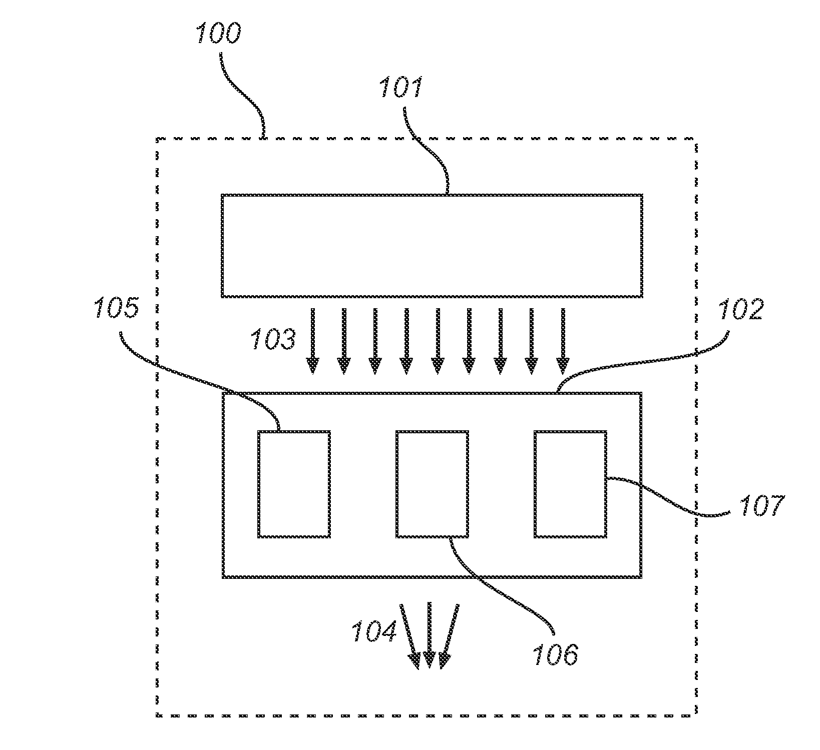
[0060]Referring now to FIG. 1, there is shown a schematic block diagram of a lighting system 100 according to an embodiment of the present invention. The lighting system 100 comprises a light-emitting module 101 and an optical element 102.

[0061]The light-emitting module 101 is adapted to emit a light field 103 having a predefined uniformity of directionality. The optical element 102 is arranged so as to receive a portion of...


PUM


Abstract

A lighting system (100) is disclosed. The lighting system (100) comprises a light-emitting module (101) adapted to emit a light field (103) having a pre-defined uniformity of directionality and an optical element (102) arranged so as to receive a portion of the light field (103) emitted by the light-emitting module (101) and configured to output a modified light field (104) based on the received light field (103). The optical element (102) is separately arranged with respect to the light-emitting module (101) and configured to modify the light field (103) input into the optical element (102) such that light field (104) output from the optical element (102) has a changed uniformity of directionality with respect to the light field (103) emitted by the light-emitting module (101). An optical element (102) adapted to be included in the lighting system (100) is also disclosed.

Description

FIELD OF THE INVENTION[0001]The present invention generally relates to the field of lighting. Specifically, the present invention relates to a lighting system capable of modifying a portion of a light field emitted by a light-emitting module providing a light field having a predefined uniformity of directionality.BACKGROUND OF THE INVENTION[0002]It is possible to provide light having a uniform light field with respect to directionality of light rays of the light field in a location such as a room using an appropriate light source or appropriate light sources. Such light may be useful in several applications including, for example, office or retail lighting. However, in some circumstances in such applications, such a light field may be too uniformly directional for certain tasks to be performed conveniently and / or efficiently. This may be alleviated by modification of the light source or by providing additional light sources.SUMMARY OF THE INVENTION[0003]In some cases, the uniformly ...

Claims


Application Information

Patent Timeline
IPC IPC(8): G02B27/30F21V5/00F21V9/00
CPCG02B27/30F21Y2101/02F21V5/00F21V9/00F21V11/00F21V13/04F21V14/06F21Y2105/00F21Y2115/15F21Y2115/10
Inventor MURDOCH, MICHAEL JOHN
Owner KONINKLIJKE PHILIPS ELECTRONICS NV
Why Eureka
Try Eureka