

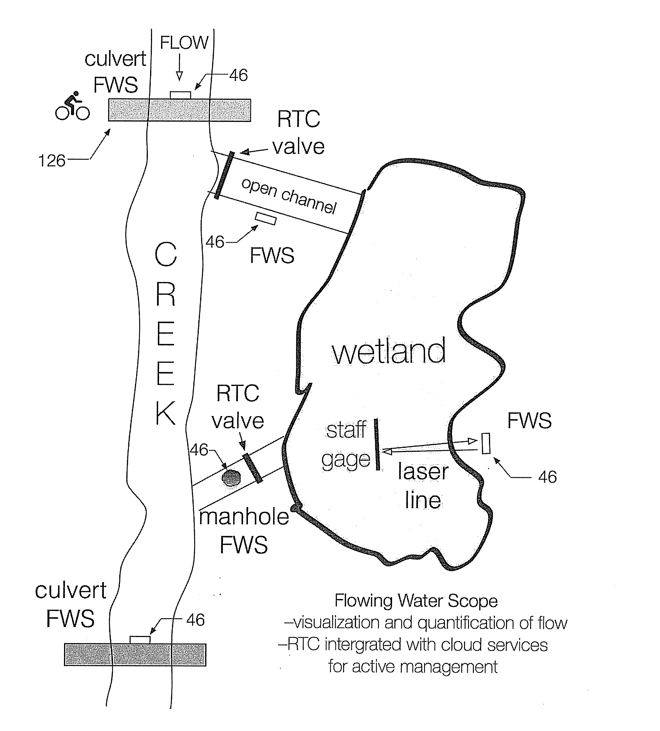
Flow imaging and monitoring for synchronized management of wide area drainage
a technology of flow imaging and monitoring, applied in the direction of volume measurement, candle holders, lighting support devices, etc., can solve the problems of high cost of methods, difficult network capability, and lack of flow monitoring systems that are easily and safely deployed
- Summary
- Abstract
- Description
- Claims
- Application Information
AI Technical Summary
Benefits of technology
Problems solved by technology
Method used
Image

Examples
Embodiment Construction
[0043]Reference will now be made in detail to the present embodiments of the present invention, examples of which are illustrated in the accompanying drawings, wherein like reference numerals refer to the like elements throughout. The embodiments are described below in order to explain the present invention by referring to the figures.
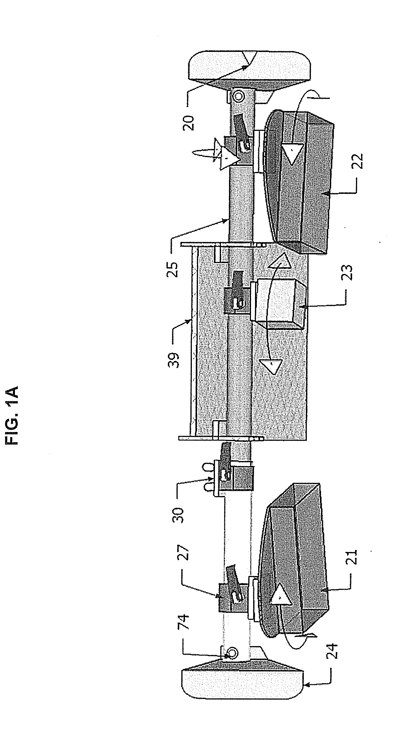
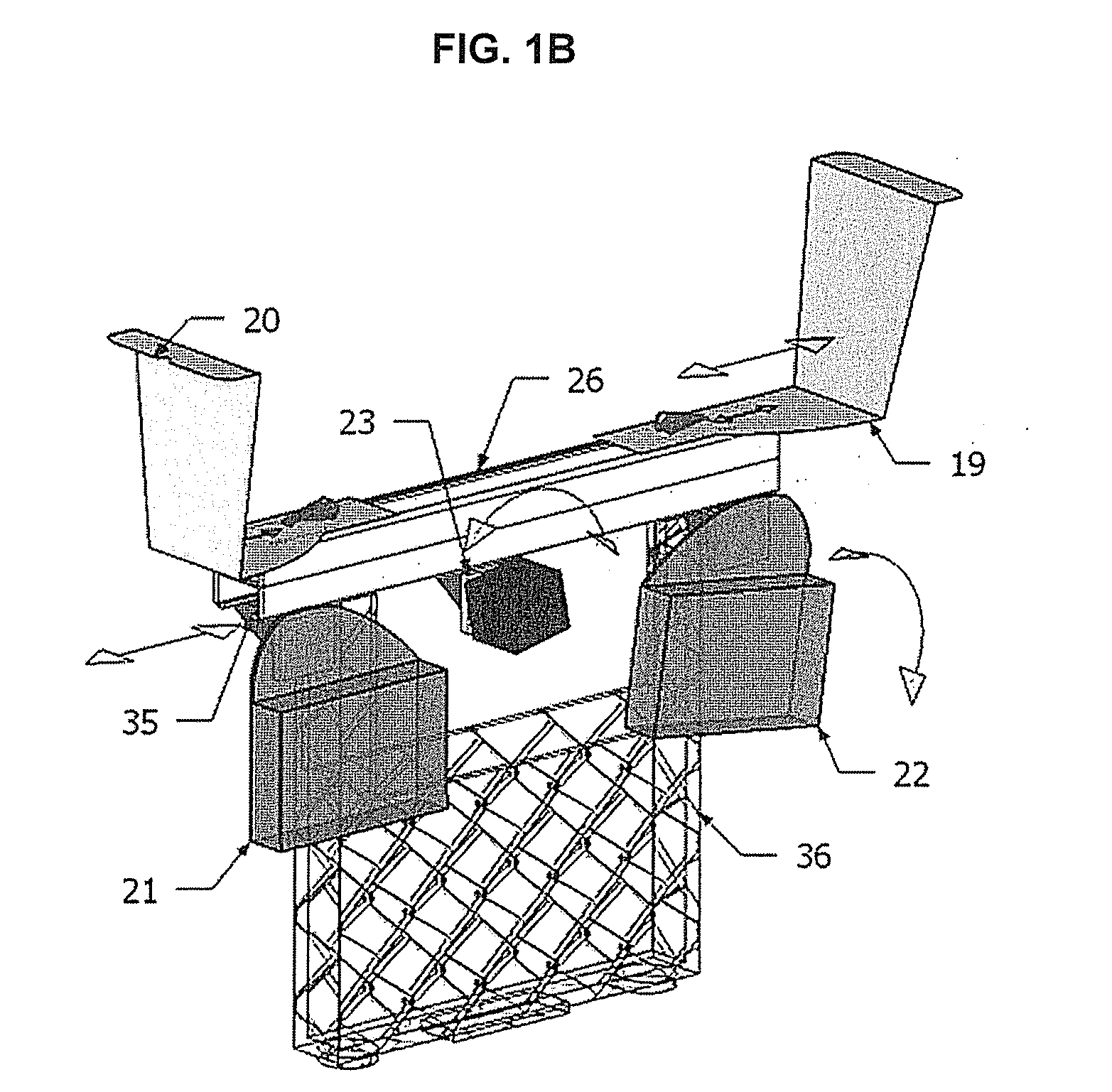
[0044]Details of the Hardware of the Interposer
[0045]As shown in FIGS. 1A-1F, an Interposer™ of the present invention includes brackets (24) that can be swapped out to match an appropriate depth beneath a sewer lid, a device to adjust fit of the interposer to the diameter of the inner ring of the manhole rim, a device for containing and supporting a battery (36, 39), clamps (27, 35) to attach enclosures (21, 22) and an accessory device (23) while allowing for manipulation in multiple planes; and drop protection (30). A system to be defined as a Flowing Water Scope™ (FWS™) includes the interposer, electronics and communications equipment contained in (2...
PUM
| Property | Measurement | Unit |
|---|---|---|
| fixed angle | aaaaa | aaaaa |
| width | aaaaa | aaaaa |
| wavelengths | aaaaa | aaaaa |
Abstract
Description
Claims
Application Information