Apparatus and method for image recognition

a technology of image recognition and apparatus, applied in the field of image recognition, can solve the problems of inconvenient re-configuration, difficult derivation of conversion equations, and too much time required for detecting the subject object, and achieve the effects of saving time and cost, convenient re-configuration, and efficient detection

Inactive Publication Date: 2015-04-02
ELECTRONICS & TELECOMM RES INST
View PDF1 Cites 18 Cited by
  • Summary
  • Abstract
  • Description
  • Claims
  • Application Information

AI Technical Summary

Benefits of technology

[0041]The above-described image recognition apparatus and method according to the present invention may configure effective candidate regions based on reference positions so that subject objects can be efficiently detected within a target image.
[0042]Also, according to the present invention, since a complex conventional camera calibration procedure is not necessary, time and cost can be saved. Also, necessary configuration can be performed on the spot immediately after installing a camera, and effective candidate regions can be easily re-configured even when a position of the camera changes.
[0043]Also, the image recognition apparatus and method according to the present invention can minimize a time required for image processing and a false detection probability so that image recognition performance can be enhanced remarkably.

Problems solved by technology

Such the method has a problem of high false detection probability and too much time required for detecting the subject object.
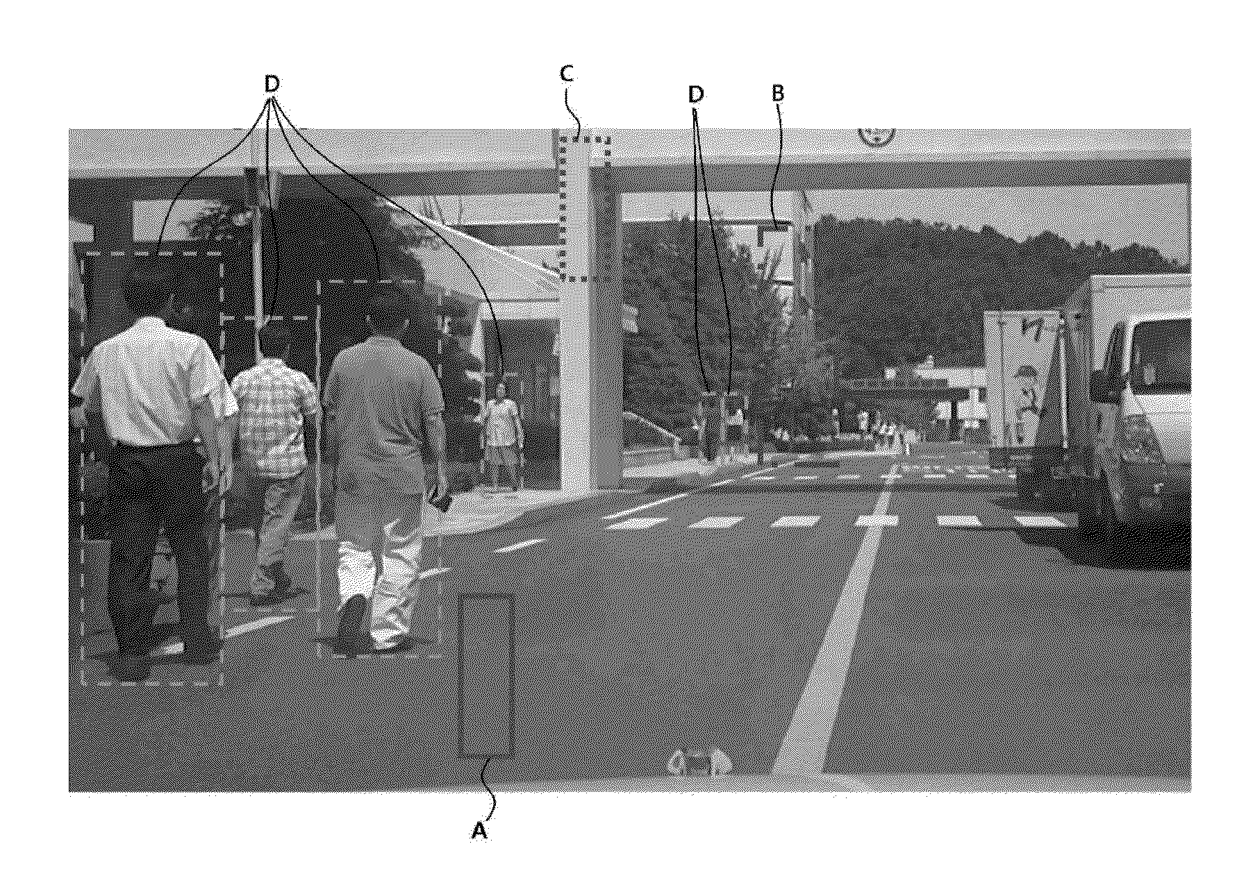
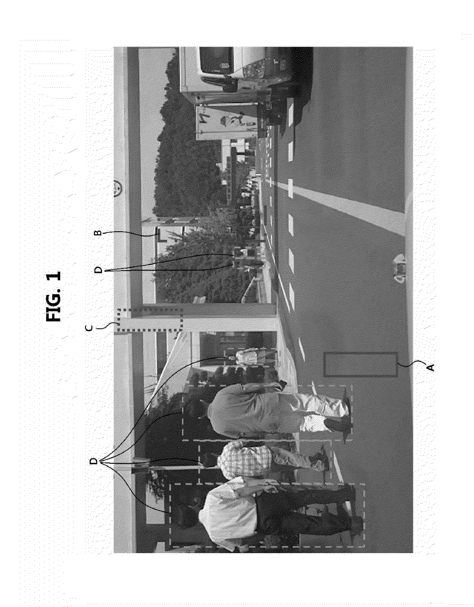
As described above, since the conventional image recognition apparatus uses a method for restricting candidate regions by using the conversion equations, there is a problem that the camera calibration procedure for deriving the conversion equations is very difficult and inconvenient.
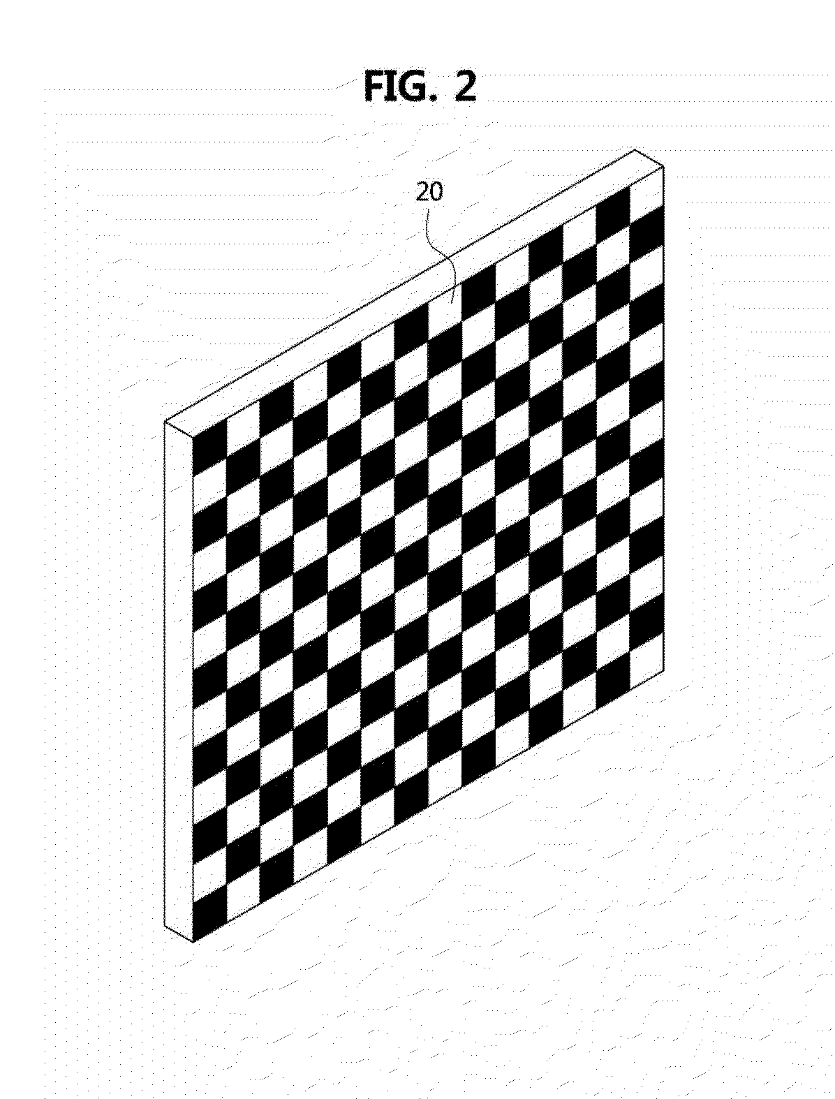
Also, since an installation height of the camera and a distance between the camera and the calibration tool 30 should be inputted on the spot, there are problems that a basic knowledge of the calibration procedure and much time are necessary and it is difficult to be performed in real time.

Method used


Image

  • Apparatus and method for image recognition
  • Apparatus and method for image recognition
  • Apparatus and method for image recognition

Examples


Embodiment Construction

[0054]Example embodiments of the present invention are disclosed herein. However, specific structural and functional details disclosed herein are merely representative for purposes of describing example embodiments of the present invention, however, example embodiments of the present invention may be embodied in many alternate forms and should not be construed as limited to example embodiments of the present invention set forth herein.

[0055]Accordingly, while the invention is susceptible to various modifications and alternative forms, specific embodiments thereof are shown by way of example in the drawings and will herein be described in detail. It should be understood, however, that there is no intent to limit the invention to the particular forms disclosed, but on the contrary, the invention is to cover all modifications, equivalents, and alternatives falling within the spirit and scope of the invention. Like numbers refer to like elements throughout the description of the figures...


PUM


Abstract

Disclosed are image recognition apparatuses and methods which detect subject objects by configuring effective candidate regions for the subject objects in a target image. The apparatus includes an image inputting part receiving at least one image; an effective candidate region configuring part configured to receive a user input including information on reference positions of effective candidate regions and an upper limit and a lower limit of the effective candidate regions, and to configure the effective candidate regions based on the user input; and an effective region determining part configured to select an effective region meeting a preconfigured threshold among the effective candidate regions configured based on the user input. Therefore, since a complex conventional camera calibration procedure is not necessary, time and cost can be saved.

Description

CLAIM FOR PRIORITY[0001]This application claims priority to Korean Patent Application No. 10-2013-0116018 filed on Sep. 30, 2013 in the Korean Intellectual Property Office (KIPO), the entire contents of which are hereby incorporated by references.BACKGROUND[0002]1. Technical Field[0003]Example embodiments of the present invention relate to a technique of image recognition and more specifically to an image recognition apparatus and method for recognizing a subject object by configuring an effective region of the subject object in a target image.[0004]2. Related Art[0005]Recently, application domains of image recognition technologies and importance of them are increasing. For example, a black-box system which recognizes images by using a camera attached in a car and records them is being used as a safety device which can realize safe driving by detecting pedestrians and other cars around the car.[0006]Generally, image recognition systems determine whether a subject object exists in an...

Claims


Application Information

Patent Timeline
Patent Type & Authority Applications(United States)
IPC IPC(8): G06K9/62H04N7/18G06V10/143
CPCH04N7/181G06K9/6202G06V10/143G06V10/255G06V10/945G06T7/00G06F18/40
Inventor LEE, JAE YEONG
Owner ELECTRONICS & TELECOMM RES INST
Why Eureka
Try Eureka