
Method and devices for synchronization

a synchronization and device technology, applied in the field of synchronization devices, can solve the problems of local interference between channel frequencies, mutual interference with neighboring base stations, and call drop, and achieve the effect of reducing the overall user experien

Active Publication Date: 2015-04-02
KHALIFA UNIV OF SCI & TECH +2
View PDF8 Cites 47 Cited by
  • Summary
  • Abstract
  • Description
  • Claims
  • Application Information

AI Technical Summary

Benefits of technology

The patent describes a method and apparatus for synchronizing the frequency and time of a slave clock in a slave device with a master clock in a master device over an Ethernet network. The method involves sending timing messages from the master device to the slave device and recording the time of receipt of the messages using the slave clock. The recorded time is then used to calculate the forward and reverse variable delays associated with the messages. These delays are then used to estimate the noise associated with the messages and adjust the actual time of the slave clock to synchronize it with the master clock. The technical effect of this invention is to provide a reliable and accurate method for synchronizing clocks in devices connected over a network.

Problems solved by technology

Without synchronization traceable to a highly accurate reference clock in the wireless network, local interference between channel frequencies, as well as mutual interference with neighboring base stations will occur.
This could ultimately cause calls to be dropped and a degradation of the overall user experience.
With frequency synchronization provided, the only issue here is determining the time offset between slave and master clocks.
However, even for time offset determination, the problem here is that IEEE 1588 PTP messages are still exposed to the PDVs inherent in the packet network even though frequency synchronization is available through Sync-E.
PDV therefore still makes time synchronization a challenge even though the frequency synchronization aspect is solved.
Packet network devices such as switches and routers introduce a variable delay to packets (PDV) that inhibits accurate path delay measurements and clock synchronization.
Even for techniques that do not require path delay measurements for clock (e.g., frequency) synchronization, the PDV is a direct contributor to the noise in the recovered clock.
The PDV inherent in packet networks is a primary source of clock noise.
The higher the clock noise, the poorer the clock quality rendering the recovered clock sometimes unusable for end system applications when the noise exceeds application defined thresholds.
For instance, for time synchronization, the variation in delay from packet to packet through the network induces noise in the slave's perception of the time at the master.
Constant delay (assuming frequency synchronized clocks) would cause a fixed offset, however variable delay causes a varying estimate of the offset.
In fact, the 10 Mb / s Ethernet (10BASE-T) is not even capable of synchronization signal transmission over the physical layer interface because a 10BASE-T transmitter stops sending pulses during idle periods.
Of course, such infrequent pulses are not sufficient for clock recovery at the receiver.

Method used


Image

  • Method and devices for synchronization
  • Method and devices for synchronization
  • Method and devices for synchronization

Examples


Embodiment Construction

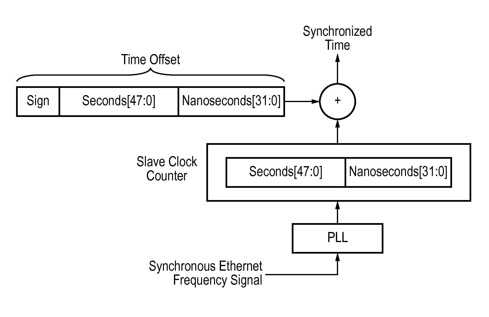
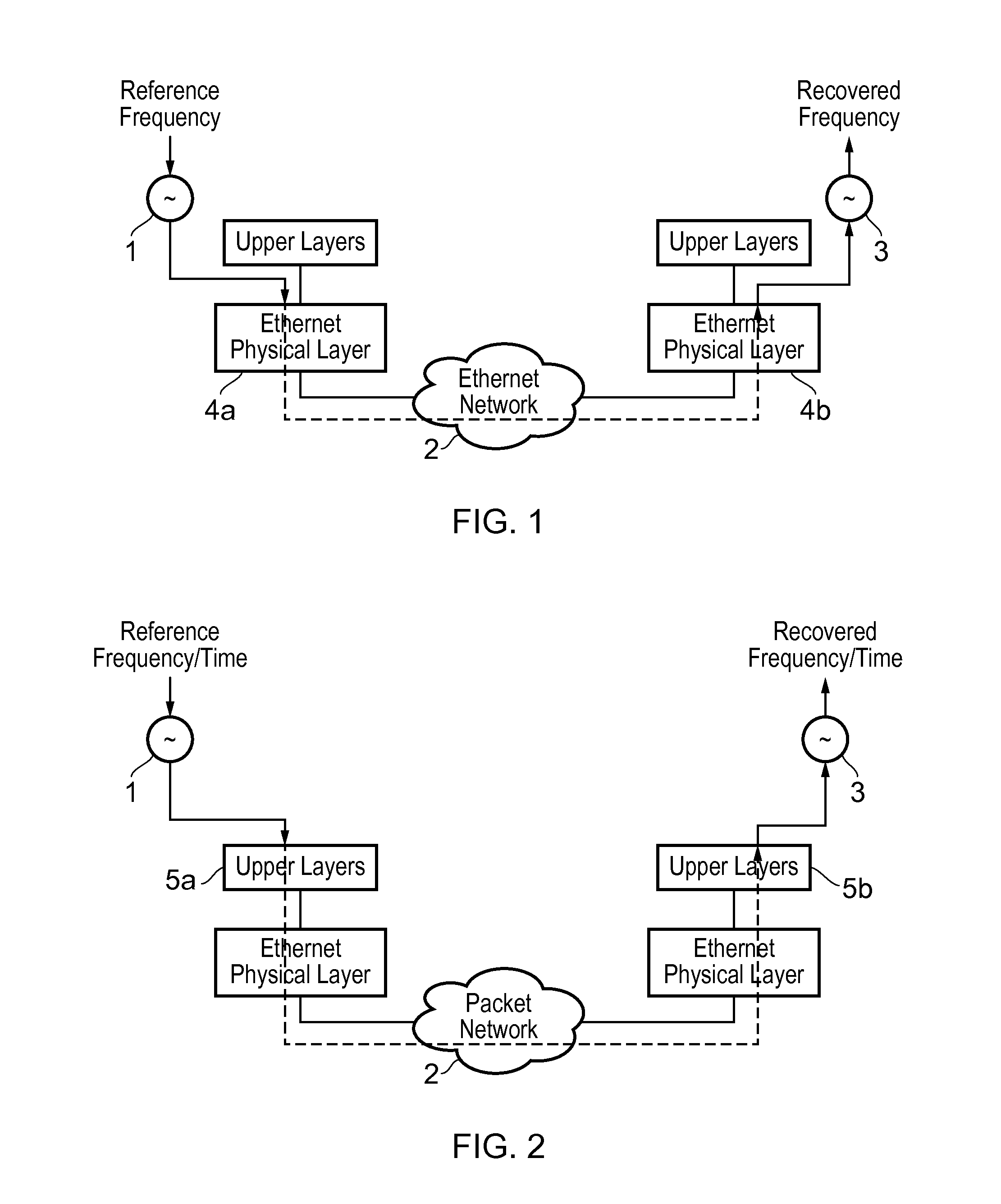
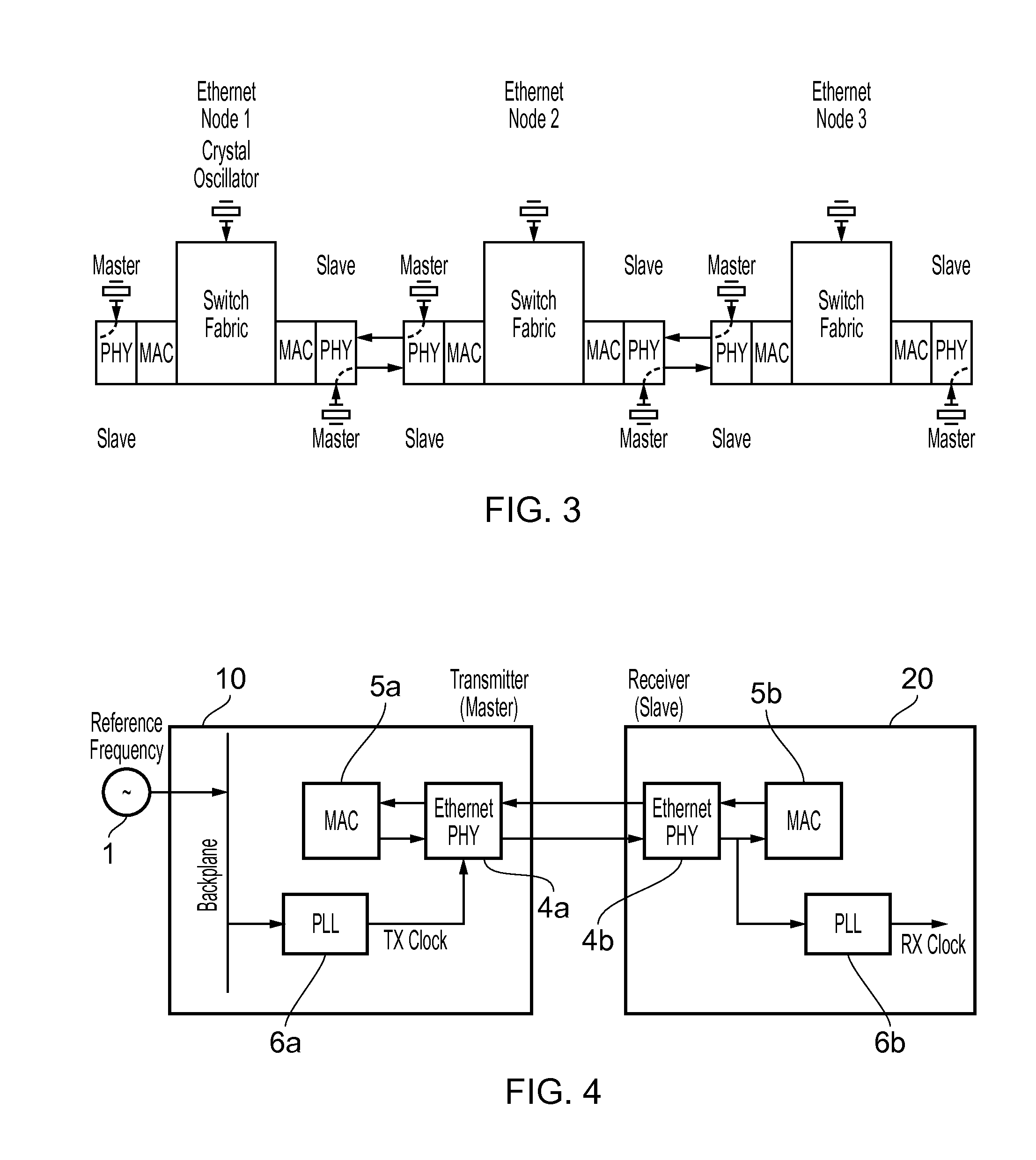
[0044]Accordingly, at their broadest, methods of the present invention provide for synchronising the time and frequency of a clock in a slave device to the time and frequency of a master clock in a master device by using both Synchronous Ethernet communications and additional timing messages.

[0045]A first aspect of the present invention provides a method of synchronising the frequency and time of a slave clock in a slave device to a master clock in a master device, wherein the master device and the slave device are connected by an Ethernet network, the method including the steps of: synchronising the frequency of the slave clock to that of the master clock using Synchronous Ethernet communications between the master device and the slave device; receiving in the slave device first and second timing messages sent from the master device and respective first and second timestamps being the time of sending of the first and second messages according to the master clock, and recording the ...


PUM


Abstract

This invention relates to methods and devices for time and frequency synchronization. The invention has particular application where time and frequency synchronization over packet networks using, for example, the IEEE 1588 Precision Time Protocol (PTP) is being carried out. The primary challenge in clock distribution over packet networks is the variable transit delays experienced by timing packets, packet delay variations (PDVs). Embodiments of the invention provide a method for time offset alignment with PDV compensation where a synchronized frequency signal is available at a slave device via Synchronous Ethernet and is used to determine the compensation parameters for the PDV.

Description

FIELD OF THE INVENTION[0001]The present invention relates to methods and devices for synchronization. It is particularly, but not exclusively, concerned with time synchronization over packet networks using, for example, the IEEE 1588 Precision Time Protocol (PTP) and synchronous Ethernet.BACKGROUND OF THE INVENTION[0002]There are many applications of high precision time synchronization over packet networks based on packet technologies like IP and Ethernet. Synchronization is a key requirement in telecommunication networks and the telecommunication industry has become a driving force in the development and evolution of synchronization solutions and standards. For example, wireless technologies like GSM, UMTS (both frequency division duplexing (FDD) and time division duplexing (TDD) versions of the UMTS technologies), and CDMA2000 require frequency accuracy of 0.05 ppm (parts per million) at the air interface.[0003]In addition, CDMA2000 requires time synchronization at the ±3 μs level...

Claims


Application Information

Patent Timeline
IPC IPC(8): H04L7/00
CPCH04L7/0033H04J3/0667H04J3/0685
Inventor AWEYA, JAMES
Owner KHALIFA UNIV OF SCI & TECH
Learn More