Multifunctional cell for structural applications

a multi-functional, cell technology, applied in the direction of cell components, sustainable manufacturing/processing, batteries, etc., can solve the problems of significant constraints on the shape and size of the device, battery consumption a significant portion of the mass and volume allocated to the device, and the effect of adding weight and/or volume is not beneficial

Active Publication Date: 2015-04-02
BATTELLE MEMORIAL INST
View PDF5 Cites 37 Cited by
  • Summary
  • Abstract
  • Description
  • Claims
  • Application Information

AI Technical Summary

Benefits of technology

[0006]An electrochemical device comprises one or more anode, cathode, and separator. In addition it has two or more current collectors. In some embodiments, the separator is also an electrolyte. The anode and cathode are between the two current collectors and each is adhered to an adjacent current collector. The separator is between the anode and cathode and adhered to the anode and cathode. The current collectors are a barrier, and are sealed together to create a sealed container for the anode, cathode, and separator. The electrochemical device may be integrated into a composite or polymer panel suitable for uses such as structural load bearing panels or sheets for aircraft wings or fuselage, composite armor, unmanned underwater vehicle, torpedo, missile body, consumer electronics, etc. The electrochemical device may include, but is not limited to, energy storage (batteries, supercapacitors), and energy generation (fuel cells).

Problems solved by technology

The energy needed for many devices and applications leads to the batteries consuming a significant portion of the mass and volume allocated to the device, and also imposes significant constraints on the shape and size of the device.
There are however, more instances where added weight and or volume are not beneficial.
However, this after-the-fact approach is not optimal.
However, due to numerous problems with the composite resin, the carbon mat thickness, the need for vapor barriers and electrolytes, the efforts were never commercially successful.

Method used


Image

  • Multifunctional cell for structural applications
  • Multifunctional cell for structural applications
  • Multifunctional cell for structural applications

Examples


example 1

Fabrication of a Structural Battery

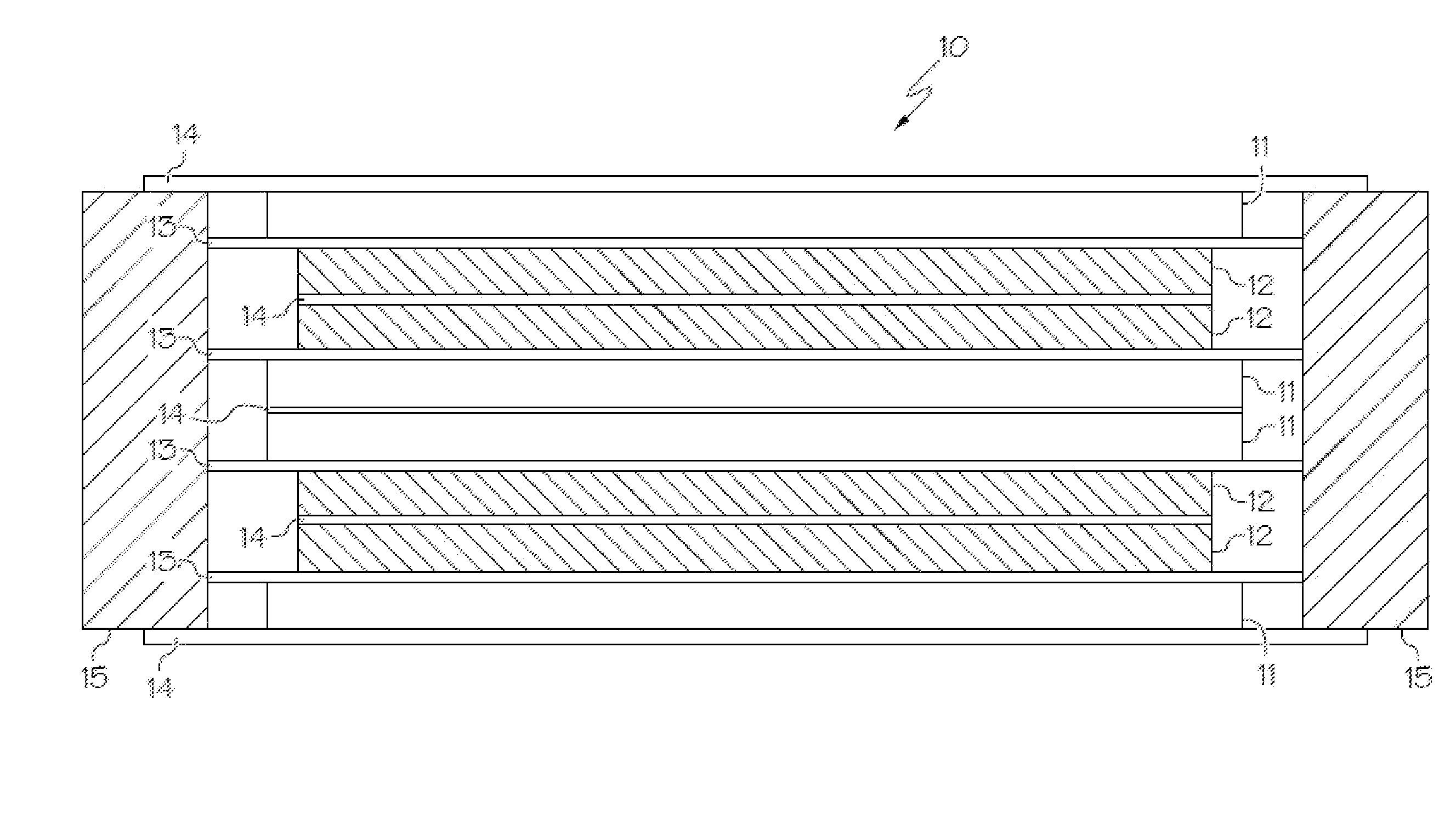
[0061]A structural battery design consists of a Li-ion bi-cell that incorporates:[0062]Two-bonded microporous polymeric separators[0063]Two outer single sided anodes with 10 micron copper foil current collector[0064]One double sided cathode with 15 micron aluminum foil current collector[0065]Liquid LiPF6 / mixed carbonate electrolyte absorbed into the electrodes and separator.

[0066]The outside anodes were cut from commercial stock, and the perimeter was cleaned using NMP to form the area for the perimeter seal. Next, two picture frame seals (with one extended side) were cut from 3 mil Suryln® film. The picture frames were then heat sealed to the anodes. Two pieces of Freya Energy safety separator modified by the manufacturer to improve adhesion and provide higher temperature tolerance were cut about 10 mm larger than the cathode. A double sided commercial cathode was cut to shape with a terminal so it extends beyond the perimeter of the anode. The ca...

example 2

Fabrication of Structural Cell with Perimeter Welded Outer Current Collectors

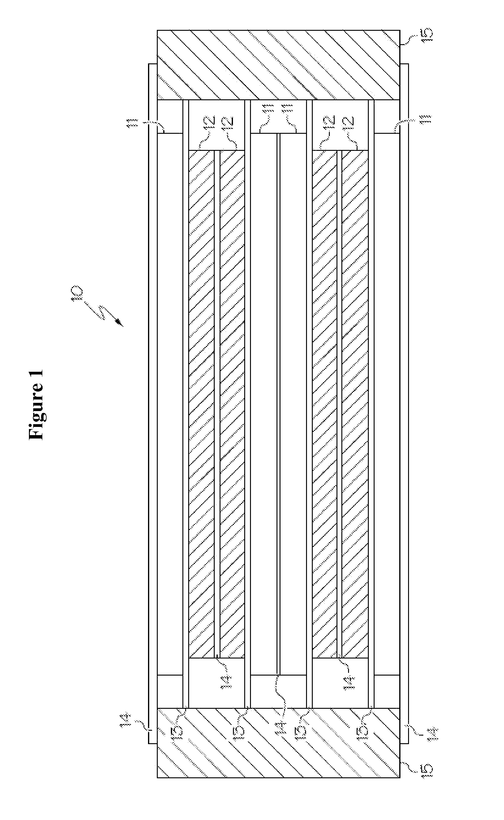
[0070]A structural battery design, as shown in FIG. 8, consists of a Li-ion bi-cell that incorporates:[0071]Two-bondable microporous polymeric separators[0072]Two outer single sided cathode with 25 micron aluminum foil current collector[0073]One double sided anode with 10 micron copper foil current collector[0074]Liquid LiPF6 / mixed carbonate electrolyte absorbed into the electrodes and separator.

[0075]The outside current collector was cut to size. The current collector may be two pieces or one piece folded. The cathode slurry was then patch coated by applying masking tape to the perimeter of the current collector and drawing down the slurry over the masked foil. The cathodes were then dried. Two pieces of special Freya Energy safety separator with improved adhesion and higher temperature tolerance were cut to size (about 10 mm larger than the anode). A double sided anode or hand coated double sided anode wa...

example 3

Fabrication of a Curved Battery

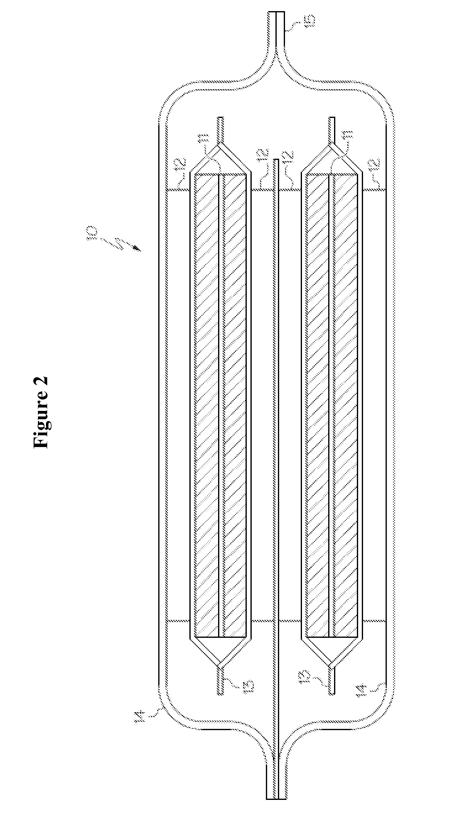
[0076]A curved structural battery design consists of a Li-ion bi-cell that incorporates:[0077]Two-bondable microporous polymeric separators[0078]Two outer single sided cathodes with 25 micron aluminum foil current collectors[0079]One double sided anode with a copper coated non-woven current collector[0080]Liquid LiPF6 / mixed carbonate electrolyte absorbed into the electrodes and separator.

[0081]The outside current collector was cut to size. The current collector may be two pieces or one piece folded. If the current collected is folded, the folded edge cannot be along the curve edge. The cathode slurry was then patch coated using a patterned screen (like silk screening) and drawing down the slurry over the screen. The cathodes were then dried and calendared. Two pieces of special Freya Energy safety separator with improved adhesion and higher temperature tolerance were cut to size (about 10 mm larger than the anode). A double sided anode was made by cutt...


PUM

PropertyMeasurementUnit
thicknessaaaaaaaaaa
sizeaaaaaaaaaa
pressureaaaaaaaaaa

Abstract

An electrochemical device comprises one or more anode, cathode, and separator. In some embodiments, the separator is also an electrolyte. In addition it has two or more current collectors. The anode and cathode are between the two current collectors and each is adhered to an adjacent current collector. The separator is between the anode and cathode and adhered to the anode and cathode. The current collectors are a barrier, and are bonded together to create a sealed container for the anode, cathode, and separator. The electrochemical device may be integrated into a composite panel suitable for uses such as structural load bearing panels or sheets for aircraft wings or fuselage, composite armor, torpedo, missile body, consumer electronics, etc. The electrochemical device may include, but is not limited to, energy storage (batteries, supercapacitors), and energy generation (fuel cells).

Description

CROSS REFERENCE TO RELATED APPLICATIONS[0001]The present application hereby claims the benefit of the provisional patent application of the same title, Ser. No. 61 / 643,947, filed on May 8, 2012, the disclosure of which is incorporated by reference herein in its entirety.BACKGROUND[0002]Today's highly mobile world is very dependent upon portable power and portable power today is trending towards electric rather than gasoline, which means batteries or other electrochemical devices are the primary power source. The energy needed for many devices and applications leads to the batteries consuming a significant portion of the mass and volume allocated to the device, and also imposes significant constraints on the shape and size of the device. For example, a large portion of the mass of a laptop computer is contained in the battery, and the shape is fixed by the shape of the battery.[0003]Because of the space and weight taken up by batteries, engineers often try to have batteries serve mul...

Claims


Application Information

Patent Timeline
Patent Type & Authority Applications(United States)
IPC IPC(8): H01M2/02H01M10/058H01M10/12H01M10/0525H01M2/08H01M2/16H01M4/02H01M10/0585H01M50/103H01M50/105H01M50/119H01M50/186H01M50/193H01M50/414H01M50/417H01M50/423H01M50/426H01M50/489
CPCH01M2/027H01M2/08H01M2/1653H01M2220/20H01M10/12H01M10/0525H01M10/058H01M2/0262Y02E60/13H01G11/52H01G11/72H01G11/76H01G11/80H01G11/82H01M10/0413H01M10/0436H01M10/052Y10T29/49112Y02E60/10Y02P70/50H01M50/545H01M50/461H01M50/417H01M50/105H01M50/186H01M50/193H01M50/103H01M50/414H01M50/489H01M50/423H01M50/426H01M50/119H01M50/10H01M50/411H01M50/183H01M50/531H01M50/409
Inventor SAYRE, JAYRISSER, STEVENMANNING, ANDREW JAMES
Owner BATTELLE MEMORIAL INST
Why Eureka
Try Eureka