Determining a Product Vector for Performing Dynamic Time Warping

a product vector and dynamic time warping technology, applied in the field of dynamic time warping of signals, can solve the problems of time-consuming and resource-intensive signal processing applications that involve matrix multiplication and dot product computations (e, ), and the cost of direct multiplication of matrices is high in both time and resources, so as to simplify the determination of products and reduce the number of computations. , the effect of reducing the amount of memory space for storag

Inactive Publication Date: 2015-04-02
SIEMENS AG
View PDF6 Cites 4 Cited by
  • Summary
  • Abstract
  • Description
  • Claims
  • Application Information

AI Technical Summary

Benefits of technology

[0007]A need exists to increase the speed of determination of the product of the signals, therewith increasing the speed of the different mathematical computations involved therein, and the performance of the signal processing applications thereof. For example, in the context of Dynamic Time Warping, an increase in the speed of determination of the product of the two signals also increases the speed of determination of the Euclidean distances associated therewith, and thereby leading to a reduction in the time required for performing Dynamic Time Warping.
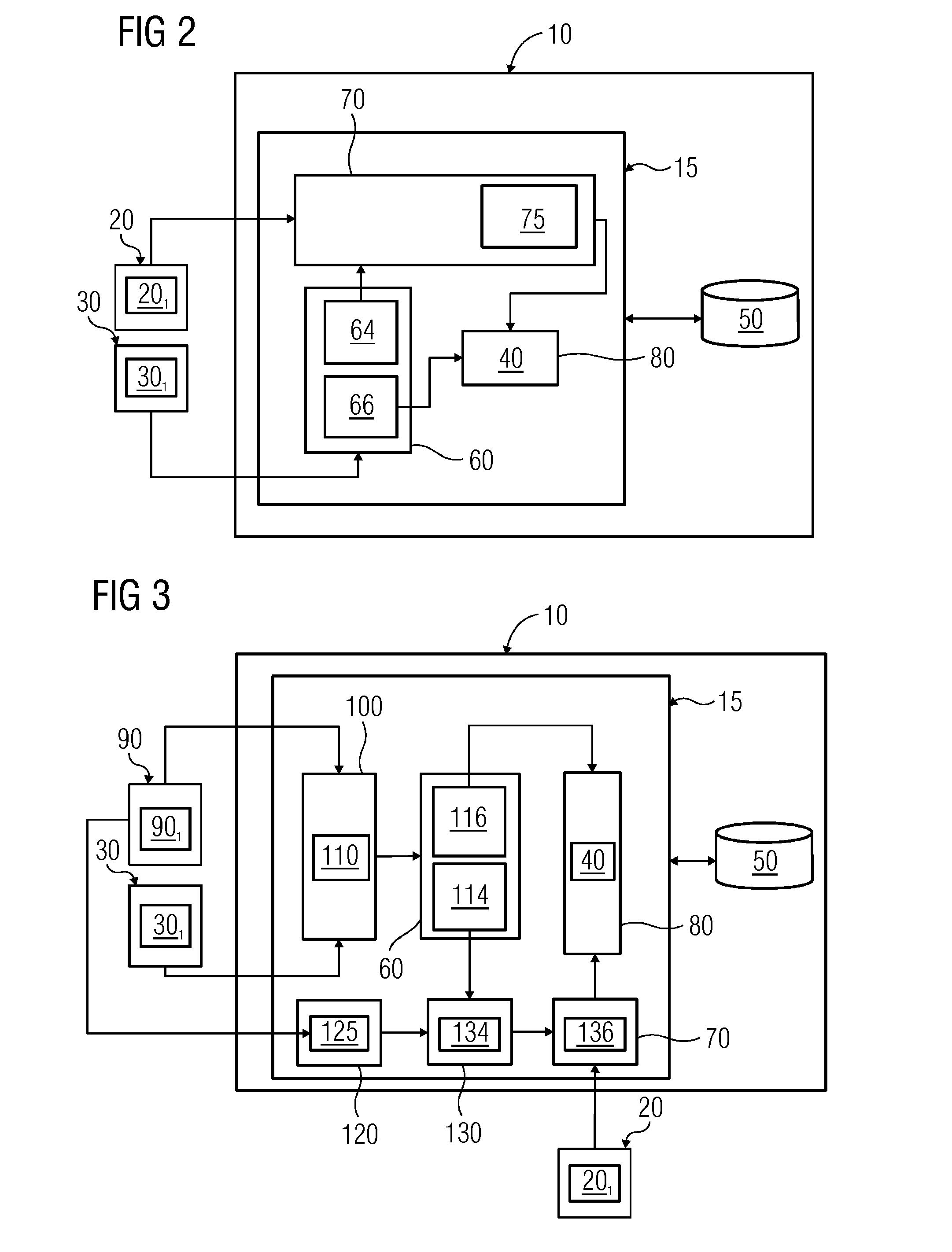
[0021]In accordance with yet another embodiment, a fourth multiplication module is provided. The multiplication of the inverse random signal and the first quasi product factorized vector is facilitated by the fourth multiplication module.

Problems solved by technology

Signal processing applications that involve matrix multiplications and dot product computations (e.g., when the matrices are of immense dimensions and / or orders) may be both time consuming and resource intensive, because of the number of multiplicative and additive operations that are to be performed for the determination of one or more intermediate results and / or the final result.
However, the direct multiplication of the matrices is expensive in terms of both time and the resources used to determine the product thereof.
Thus, the current technique poses impediments, especially for very high speed and highly data intensive applications, because latency is introduced in the determination of the final result.

Method used


Image

  • Determining a Product Vector for Performing Dynamic Time Warping
  • Determining a Product Vector for Performing Dynamic Time Warping
  • Determining a Product Vector for Performing Dynamic Time Warping

Examples


Embodiment Construction

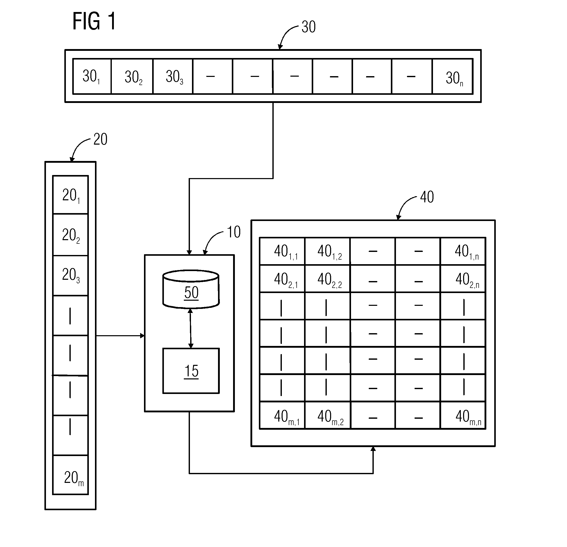
[0033]An overview of a system 10 for determining a product vector 401,1 from a test signal vector 301 and a template signal vector 201 in accordance with one or more embodiments is depicted in FIG. 1.

[0034]A plurality of test signal vectors 30 (e.g., ‘n’ number of exemplary test signal vectors 301-30n) is depicted in FIG. 1. Each test signal vector 301-30n includes vectorized values of at least a portion of a test signal (not shown) (e.g., the vectorized values of the test signal vector 301-30n may correspond to respective discrete-time sampled values of the portion of the test signal). The test signal may correspond to a discrete-time signal, such as a discrete-time speech signal, a discrete-time video signal, a discrete-time image signal, a discrete-time temperature signal, etc.

[0035]An exemplary manner of obtainment of the ‘n’ number of exemplary test signal vectors 301-30n is discussed below. The test signal may be windowed in time domain, where a certain time domain window of t...


PUM


Abstract

A method and a system for determining a product vector for computation of a Euclidean distance for performing dynamic time warping of a test signal and a template signal are provided. Low-rank factorized vectors for the test signal are determined. The low-rank factorized vectors are processed along with the template signal for determining the product vector. The product vector is thereafter usable for the determination of a Euclidean distance between the test signal and the template signal, and for performing dynamic time warping of the test signal and the template signal.

Description

[0001]This application claims the benefit of IN 1130 / KOL / 2013, filed on Sep. 30, 2013, which is hereby incorporated by reference in its entirety.BACKGROUND[0002]The present embodiments relate to Dynamic Time Warping of signals.[0003]Modem day signal processing applications, such as Dynamic Time Warping, Data Compression, Data Indexing, Image Processing, etc., involve tremendous amounts of data processing. The different signals involved may be represented as matrices, which comprise a vast multitude of vectors. The data processing involved includes mathematical computations and mathematical transformations, such as matrix additions, matrix multiplications, matrix inversions, determination of Fast Fourier Transforms, etc. Signal processing applications that involve matrix multiplications and dot product computations (e.g., when the matrices are of immense dimensions and / or orders) may be both time consuming and resource intensive, because of the number of multiplicative and additive o...

Claims


Application Information

Patent Timeline
Patent Type & Authority Applications(United States)
IPC IPC(8): G06F17/16
CPCG06F17/16G06V10/7515
Inventor GAJJAR, MRUGESHVYDYANATHAN, NAGAVIJAYALAKSHMI
Owner SIEMENS AG
Why Eureka
Try Eureka