
Magneto-caloric effect element and thermo-magnetic cycle apparatus

Active Publication Date: 2015-04-09
DENSO CORP
View PDF14 Cites 29 Cited by
  • Summary
  • Abstract
  • Description
  • Claims
  • Application Information

AI Technical Summary

Benefits of technology

The present disclosure provides a magneto-caloric effect element and a thermo-magnetic cycle apparatus with high effectiveness, even if there is a difference in magneto-caloric-effect in a part of the element units. It achieves this by setting the size of the element unit and / or Curie temperature of the element unit so that the boundary temperature and the cross temperature may coincide with each other. This allows regions higher than the crossing point of a plurality of performance distributions to be used in the rated operational status, even if the heights of the performance distributions of a plurality of element units differ at least in a part thereof.

Problems solved by technology

However, it may be difficult to obtain the element units which fulfill such conditions.
However, there are difficulties in providing an element unit having a required performance from various viewpoints.
For example, several technical obstructions, such as a restriction of the material which can be used, a restriction of the ratio which can be adjusted, and a restriction of parameters which can be adjusted in the manufacturing process, may make it difficult to achieve a required element unit.
In another viewpoint, cost may make it difficult to achieve a required element unit.
If a desirable element unit is not available, the plurality of element units arranged in series cannot demonstrate a high performance.
For example, if there is a certain difference between the magneto-caloric effects demonstrated by two element units arranged adjacently along a temperature gradient, one of the element units may not be able to perform within a high performance temperature range in which the element unit can demonstrate a high magneto-caloric effect.

Method used


Image

  • Magneto-caloric effect element and thermo-magnetic cycle apparatus
  • Magneto-caloric effect element and thermo-magnetic cycle apparatus
  • Magneto-caloric effect element and thermo-magnetic cycle apparatus

Examples


first embodiment

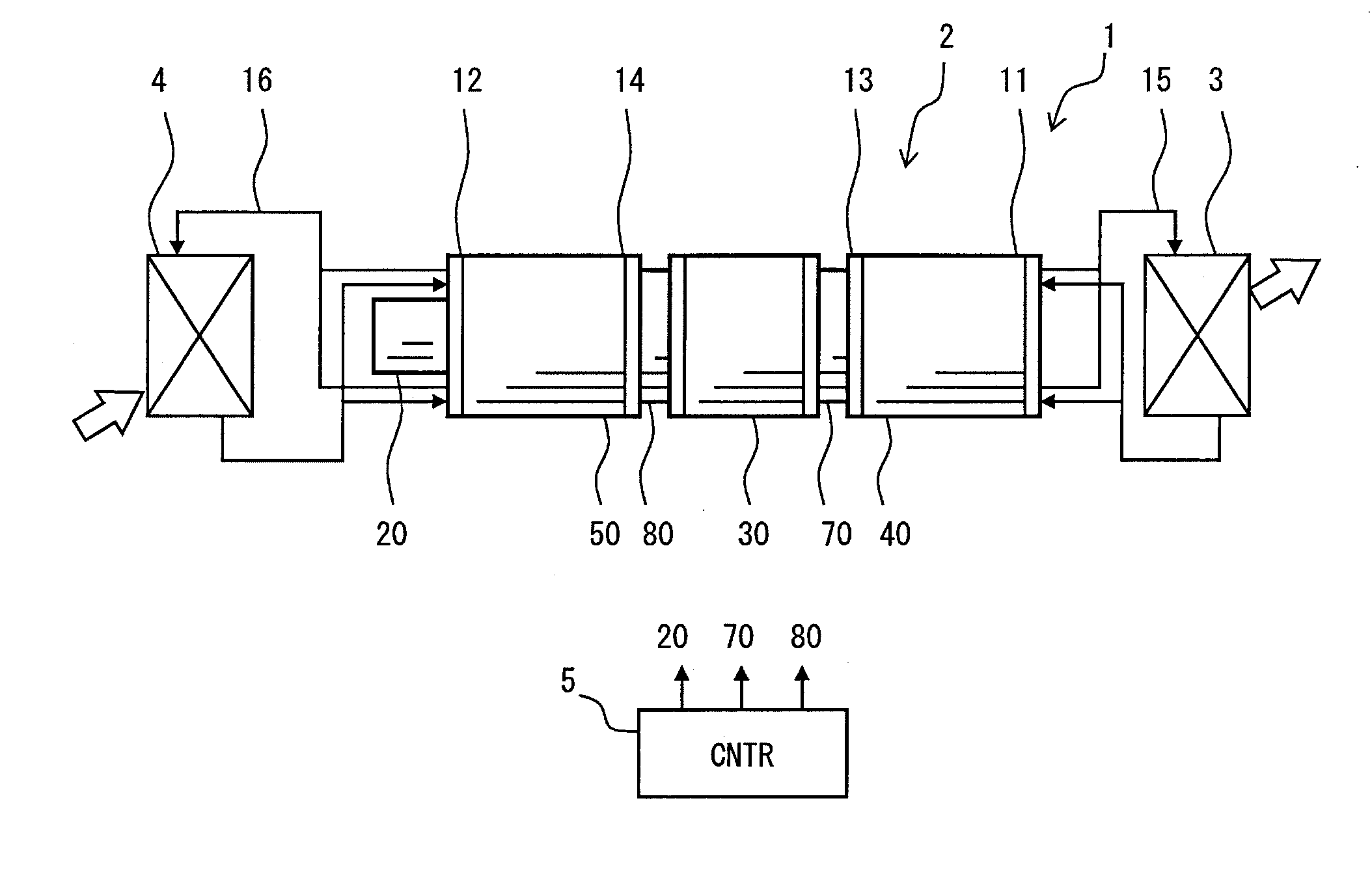
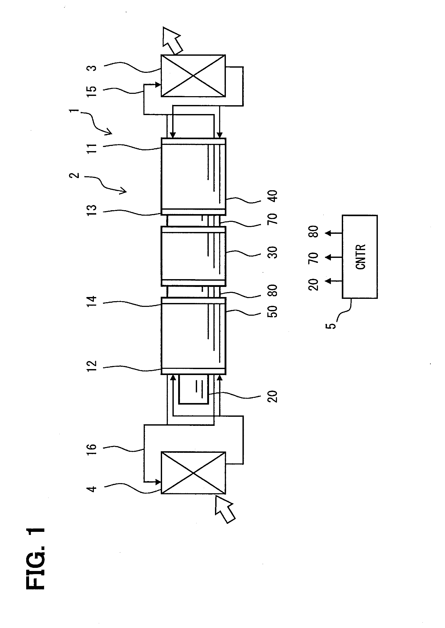
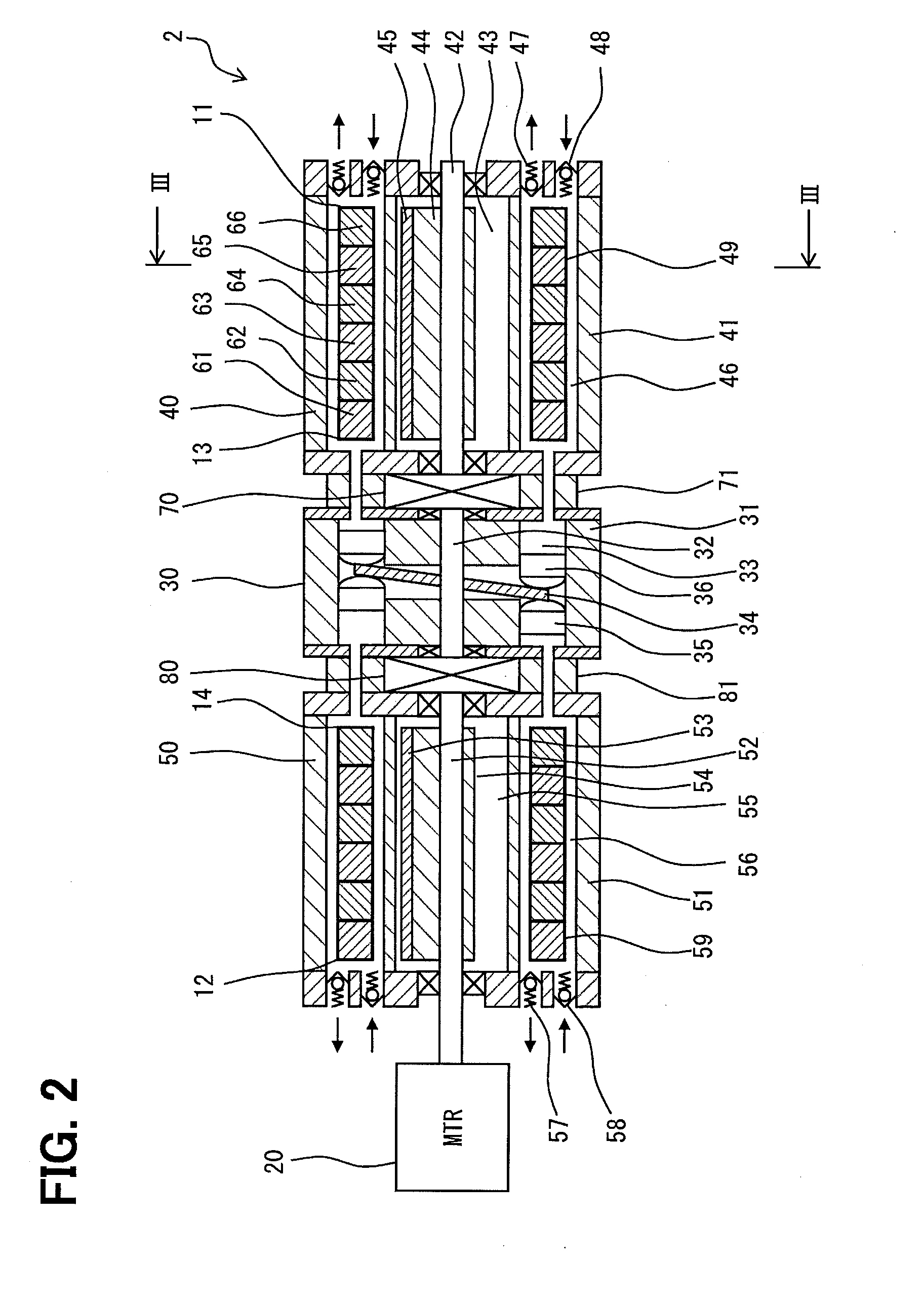
[0031]FIG. 1 is a block diagram showing a vehicle air-conditioner 1 having a magneto-caloric effect type heat pump apparatus according to a first embodiment of the present disclosure. The magneto-caloric effect type heat pump apparatus 2 may be referred as an MHP 2. The vehicle air-conditioner 1 is mounted on a vehicle, and adjusts a temperature of passenger's cabin. The vehicle air-conditioner 1 has two heat exchangers 3 and 4. The heat exchanger 3 is a high-temperature side heat exchanger which becomes higher in temperature than that of the heat exchanger 4. The heat exchanger 4 is a low-temperature side heat exchanger which becomes lower in temperature than that of the heat exchanger 3. The vehicle air-conditioner 1 also has air handling system components for using the high-temperature side heat exchanger 3 and / or the low-temperature side heat exchanger 4 for air-conditioning purposes, such as an air conditioning duct and a blower.

[0032]The vehicle air-conditioner 1 is used as a ...

second embodiment

[0099]This embodiment is one of modifications based on a basic form provided by the preceding embodiment. In the above-mentioned embodiment, the boundary temperature and the cross temperature are adjusted to coincide each other by adjusting the lengths of the element units. Alternatively, in this embodiment, the boundary temperature and the cross temperature are adjusted to coincide with each other by selecting and adjusting Curie temperatures of the element units. Curie temperature of an element unit can be adjusted with various approaches, such as selecting material used, adjusting a material ratio, and adjusting a manufacturing process. In this embodiment, the structure shown in FIG. 1-FIG. 3 is employed. An MCE 249 illustrated in FIG. 8 is used.

[0100](MCE for Second Embodiment)

[0101]FIG. 8 shows the MCE 249 which can be used as the MCE 49 and 59. As shown in a diagram (a), the MCE 249 has the element units 61-66. The element units 61-66 have the same length La.

[0102]As shown in ...

third embodiment

[0112]This embodiment is one of modifications based on a basic form provided by the preceding embodiment. In the above-mentioned embodiment, the boundary temperature and the cross temperature are adjusted to coincide each other by adjusting the lengths of the element units or Curie temperatures of the element units. Alternatively, in this embodiment, the boundary temperature and the cross temperature are adjusted to coincide with each other by selecting and adjusting both the lengths of the element units and Curie temperatures of the element units. In this embodiment, the structure shown in FIG. 1-FIG. 3 is employed. An MCE 349 illustrated in FIG. 9 is used.

[0113](MCE for Third Embodiment)

[0114]FIG. 9 shows the MCE 349 which can be used as the MCE 49 and 59. As shown in a diagram (a), the MCE 349 has the element units 61-66. In the illustrated example, a plurality of element units 61-66 have different lengths L1-L6, respectively. As shown in a diagram (b), Curie temperatures Tc1-Tc6...


PUM


Abstract

A magneto-caloric-effect element has a plurality of element units. The element units have lengths, respectively. The element units have different Curie temperatures, respectively. The element units demonstrate magneto-caloric effects. Two adjoining performance distribution crosses at a cross temperature. A temperature in the rated operational status between two adjoining element units is called a boundary temperature. The lengths and / or Curie temperatures are set so that the boundary temperatures and the cross temperatures coincide each other. Thereby, a plurality of element units can function at high effectiveness in the rated operational status.

Description

CROSS REFERENCE TO RELATED APPLICATION[0001]This application is based on Japanese Patent Application No. 2013-212272 filed on Oct. 9, 2013, the disclosure of which is incorporated herein by reference.TECHNICAL FIELD[0002]The present disclosure relates to a magneto-caloric effect element and a thermo-magnetic cycle apparatus using magneto-caloric effect of magnetic material. The magneto-caloric effect element and the thermo-magnetic cycle apparatus may be used as a magneto-caloric effect type heat pump apparatus.BACKGROUNDPatent Literatures (PLT)[0003]PLT 1: JP2012-255642A[0004]PLT 2: JP2012-229634A[0005]PLT 3: JP2012-503754A[0006]PLT 1, PLT 2, and PLT 3 disclose a plurality of element units which have different Curie temperature, and are arranged series in an order of Curie temperatures. These apparatus are appropriate for applications which have a large temperature difference between a high temperature end and a low temperature end.SUMMARY[0007]In a case of using a plurality of ele...

Claims


Application Information

Patent Timeline
IPC IPC(8): F25B21/00
CPCF25B2321/002F25B21/00B60H1/00478F25B2321/0022Y02B30/00
Inventor WATANABE, NAOKIMORIMOTO, TSUYOSHIFUSE, TAKUYA
Owner DENSO CORP
Learn More