Supercharge Your Innovation With Domain-Expert AI Agents!

Position sensor assembly in a hydraulic cylinder

a technology of position sensor and hydraulic cylinder, which is applied in the direction of machines/engines, safety/regulatory devices, constructions, etc., can solve the problems of visual observation not giving accurate output, hydraulic cylinders may be exposed to harsh environmental conditions, damage to equipment,

Inactive Publication Date: 2015-04-09
CATERPILLAR INC
View PDF2 Cites 7 Cited by
  • Summary
  • Abstract
  • Description
  • Claims
  • Application Information

AI Technical Summary

Benefits of technology

The patent text describes a position sensor assembly that is designed to protect it from the harsh environmental conditions in hydraulic cylinders. The technical effect of this is that it ensures accurate and reliable detection of position in harsh environments, which would have been difficult or even impossible without the protective measures.

Problems solved by technology

Mere visual observation may not give accurate output and may damage the equipment.
However, the hydraulic cylinders may be exposed to harsh environmental conditions.
For example, during a particular operation cycle, the cylinder may be subjected to vibrations.
The sensors may be affected by vibrations and consequently may lack absolute position sensing capabilities.

Method used


Image

  • Position sensor assembly in a hydraulic cylinder
  • Position sensor assembly in a hydraulic cylinder
  • Position sensor assembly in a hydraulic cylinder

Examples


Embodiment Construction

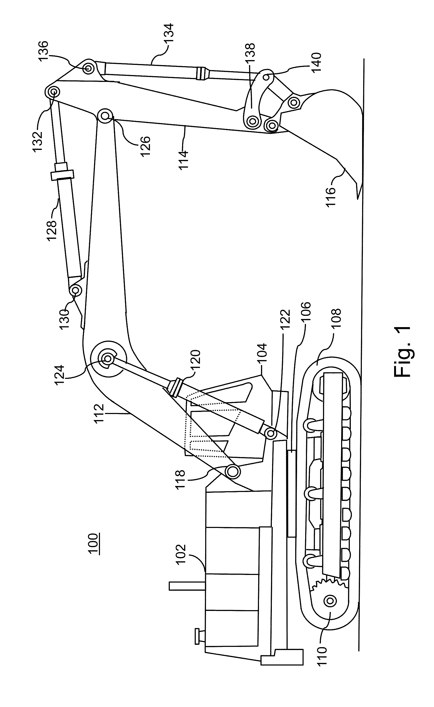
[0009]Shown in FIG. 1 is an illustration of a hydraulic excavator 100. The hydraulic excavator 100 includes an upper structure, a lower structure and a working element. The upper structure includes a rotatably mounted body 102 and an operator cab 104. The operator cab 104 can be connected to the body 102 and houses one or more control devices for controlling the operations of the hydraulic excavator 100.

[0010]The lower structure includes an undercarriage 106 supported by a pair of tracks 108 and sprocket 110. The body 102 mentioned as a part of upper structure is mounted on the undercarriage 106.

[0011]The working element comprises a boom 112, a dipper 114, a work tool 116 and a plurality of hydraulic cylinders. The boom 112 can be mounted on a pivot point 118 on a forward end of the body 102. The boom 112 can be moved vertically with the help of a hydraulic cylinder 120. A lower end of the hydraulic cylinder 120 can be pivoted to a forward end of the body 102 at a pivot point 122 an...


PUM


Abstract

A position sensor assembly for the hydraulic cylinder having a piston and piston rod is provided. The position sensor assembly includes a pressure to electric energy convertor, a transmitter and a receiver. The pressure to electric energy convertor is disposed inside the piston. The pressure to electric energy convertor is configured to determine pressures on both the sides of the piston and convert the determined pressure difference into electric current. The electric current is consumed by the transmitter and hence, the transmitter generates a signal. The signal is wirelessly transmitted to the receiver through the hydraulic cylinder. The receiver disposed on the hydraulic cylinder receives the signal through various components of the hydraulic cylinder. The signal is used to determine the position of the piston.

Description

TECHNICAL FIELD[0001]The present invention is related to hydraulic cylinders, more particularly to a position sensor assembly for sensing the position of a piston in a hydraulic cylinder.BACKGROUND[0002]Hydraulic cylinders-piston assemblies are used in different type of machines for a number of industrial applications such as construction, forestry, agriculture, mining and excavation. Different types of machines may include a wheel loader, an excavator, a track type tractor, a farm tractor, crane, paver, dozer, and the like. Traditionally, a human operator controls a hydraulic cylinder-piston assembly based on visual observation. Mere visual observation may not give accurate output and may damage the equipment. Such hydraulic cylinder-piston assemblies may be automatically controlled for predefined operating cycles. Further, for automatic control, the position / velocity of the piston needs to be determined for efficient and smooth functioning of the hydraulic cylinders-piston assembl...

Claims


Application Information

Patent Timeline
IPC IPC(8): F15B15/28
CPCF15B15/2815E02F9/2271E02F9/264
Inventor SUBRT, MICHAEL
Owner CATERPILLAR INC
Features
  • R&D
  • Intellectual Property
  • Life Sciences
  • Materials
  • Tech Scout
  • Unparalleled Data Quality
  • Higher Quality Content
  • 60% Fewer Hallucinations
Learn More