System and method for controlling rotational dynamics of a power generator

a technology of rotational dynamics and power generators, applied in the direction of electric generator control, machine/engine, asynchronous induction clutches/brakes, etc., can solve the problems of generators accelerating and running, generator tripping, load rejection may be a challenge, etc., to achieve the effect of increasing speed and simplicity

Inactive Publication Date: 2015-04-09
GENERAL ELECTRIC CO
View PDF0 Cites 3 Cited by
  • Summary
  • Abstract
  • Description
  • Claims
  • Application Information

AI Technical Summary

Problems solved by technology

Moreover, depending on the type and rating of a gas engine, load rejection may be a challenge.
Large load rejections may cause the generators to accelerate and run at over speed, which in turn may lead to tripping the generators.
When a fault occurs in the power generation system, voltage in the system may drop by a significant amount, which in turn may cause the generators to accelerate and may go off line in the system.

Method used


Image

  • System and method for controlling rotational dynamics of a power generator
  • System and method for controlling rotational dynamics of a power generator
  • System and method for controlling rotational dynamics of a power generator

Examples


Embodiment Construction

[0013]Unless defined otherwise, technical and scientific terms used herein have the same meaning as is commonly understood by one of ordinary skill in the art to which this disclosure belongs. The terms “a” and “an” do not denote a limitation of quantity, but rather denote the presence of at least one of the referenced items. The term “or” is meant to be inclusive and mean one, some, or all of the listed items. The use of “including,”“comprising” or “having” and variations thereof herein are meant to encompass the items listed thereafter and equivalents thereof as well as additional items. The terms “connected” and “coupled” are not restricted to physical or mechanical connections or couplings, and can include electrical connections or couplings, whether direct or indirect. Furthermore, the terms “circuit,”“circuitry,”“controller,” and “processor” may include either a single component or a plurality of components, which are either active and / or passive and are connected or otherwise...


PUM


Abstract

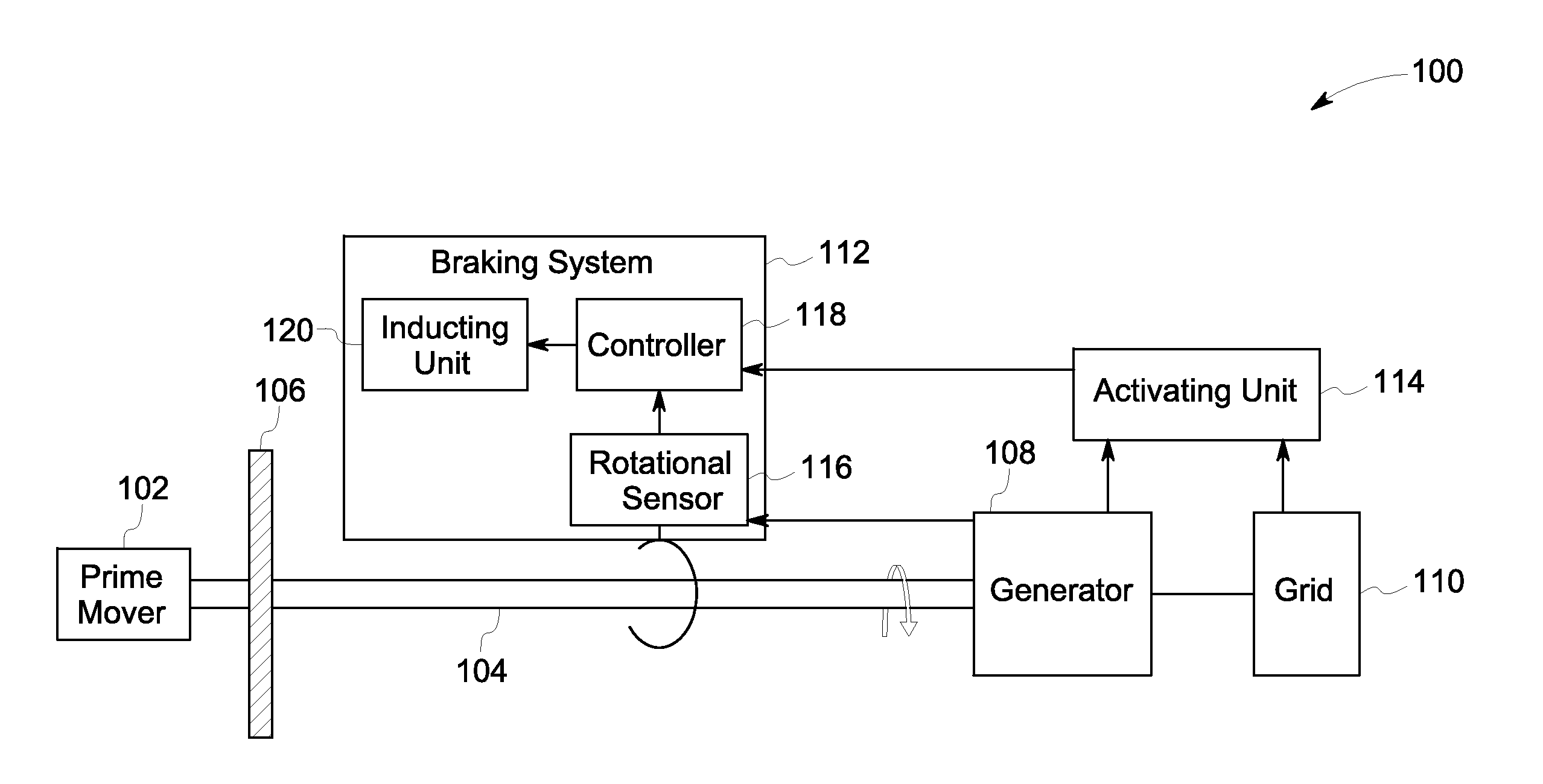
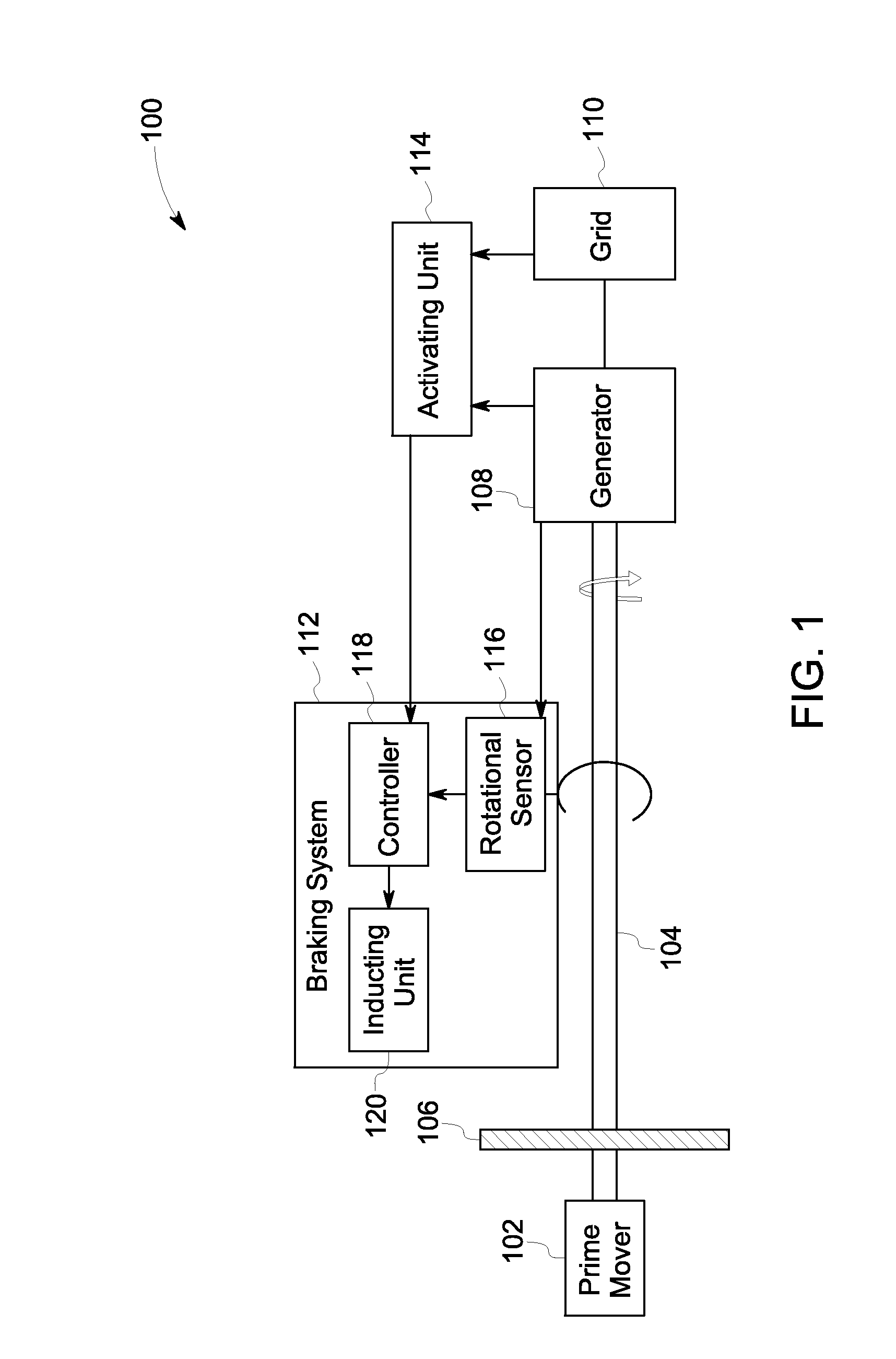
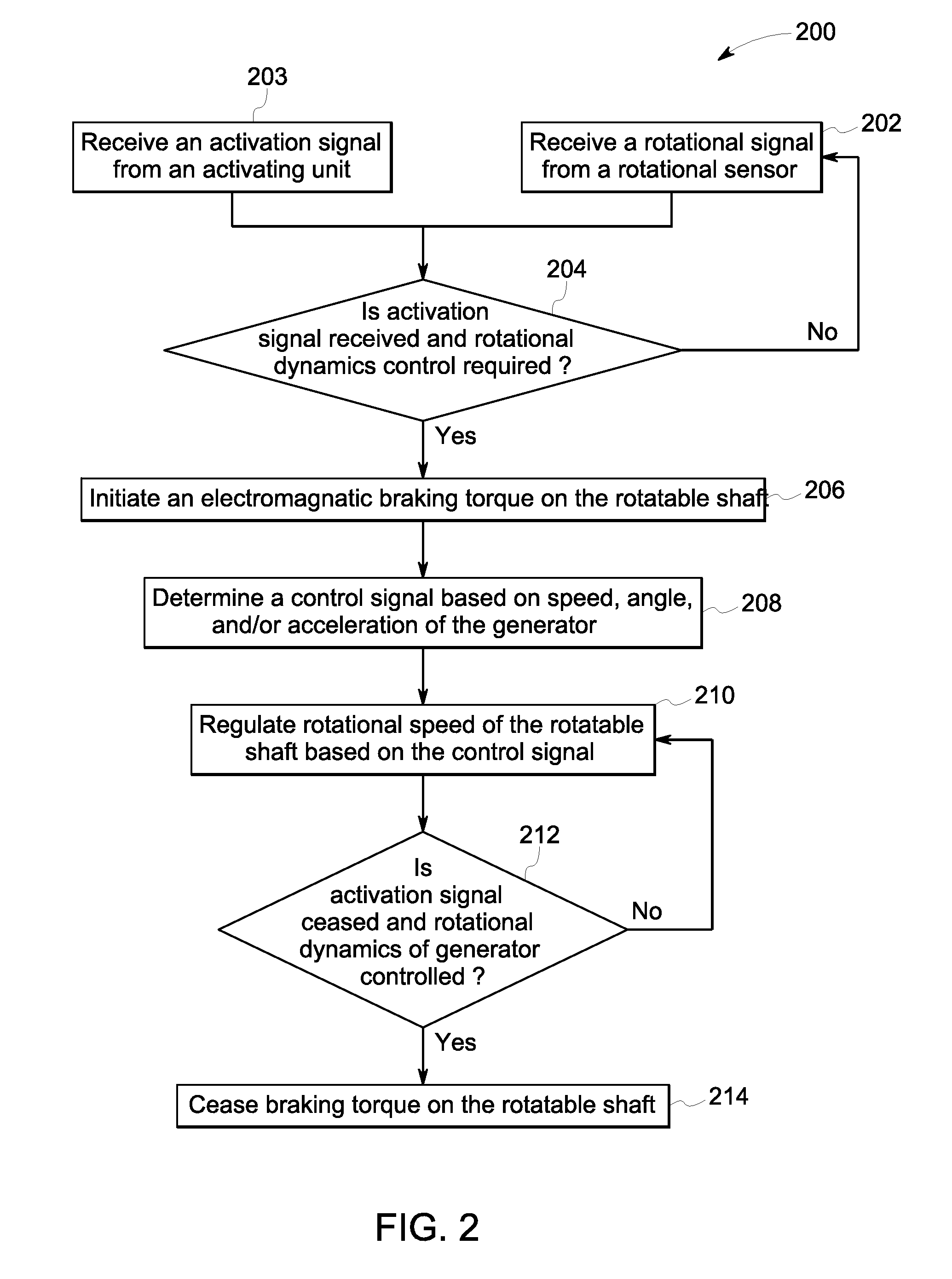
An electromagnetic braking system includes an electrically conductive disc coupled to a rotatable shaft of a power generation system. The rotatable shaft is operatively coupled to a prime mover and a generator. The electromagnetic braking system further includes an inducting unit for applying an electromagnetic braking torque on the electrically conductive disc when commanded by a control signal and a controller for receiving an activation signal from an activating unit, receiving a rotational signal from a rotational sensor coupled to the rotatable shaft or the generator, determining a control signal when the rotational signal is outside of a threshold, and, when the activation signal is active and the rotational signal is outside of the threshold, sending the control signal to the inducting unit to regulate a rotational dynamic of the rotatable shaft.

Description

CROSS REFERENCE TO RELATED APPLICATIONS[0001]This application is a continuation in part of U.S. patent application Ser. No. 13 / 536245, entitled “ELECTROMAGNETIC BRAKING SYSTEMS AND METHODS”, filed 28 Jun. 2012, published as US2014-0001756, which is herein incorporated by reference.BACKGROUND[0002]The disclosure relates generally to a power generation system and more specifically to systems and methods for controlling rotational dynamics of power generators in the power generation system.[0003]Power generation systems are widely used for generating and distributing power to one or more load devices. Particularly, in grid applications, power generators are typically used to transmit power to a power grid or to an island grid that supports one or more customer loads. Some power generators may be sized in a range from 3 kW to 10000 kW. Traditionally, smaller sized power generators have been diesel generators. However, in recent years, a growth in the use of gas generators for one or mor...

Claims


Application Information

Patent Timeline
Patent Type & Authority Applications(United States)
IPC IPC(8): H02P9/00H02K49/04
CPCH02K49/046H02P9/006F03D7/0244F03D7/0272H02P3/04H02P9/06F16D2121/20F16D2066/003Y02E10/72
Inventor PANOSYAN, ARABOELD, CHRISTOPHSCHAUMBERGER, HERBERTSCHROEDER, STEFANVOGL, LUKASAVANESOV, MIKHAIL AVRAMOVICH
Owner GENERAL ELECTRIC CO
Why Eureka
Try Eureka