
LED Backlight Module and the Corresponding Liquid Crystal Display

Active Publication Date: 2015-04-09
TCL CHINA STAR OPTOELECTRONICS TECH CO LTD
View PDF12 Cites 2 Cited by
  • Summary
  • Abstract
  • Description
  • Claims
  • Application Information

AI Technical Summary

Benefits of technology

The present invention provides an LED backlight module and liquid crystal display that saves money and resources by using less LEDs. The LED and light guide work together to create a uniform lighting, and the diffuser helps transform the spot light into line light and surface light. By reducing the distance between the LED and light guide, the backlight is improved and the narrow frame of the liquid crystal display panel is benefited. Overall, the invention provides a cost-effective and efficient solution for LED backlighting.

Problems solved by technology

However, there is a bottleneck to further reduce the energy consumption.
However, in the structure of the side-type backlight module, it would produce significant hot spots when the number of LEDs is reduce because the light mixing distance between the LED and the light guide plate is limited.

Method used


Image

  • LED Backlight Module and the Corresponding Liquid Crystal Display
  • LED Backlight Module and the Corresponding Liquid Crystal Display
  • LED Backlight Module and the Corresponding Liquid Crystal Display

Examples


Embodiment Construction

[0046]The detailed descriptions accompanying drawings and the embodiment of the present invention are as follows.

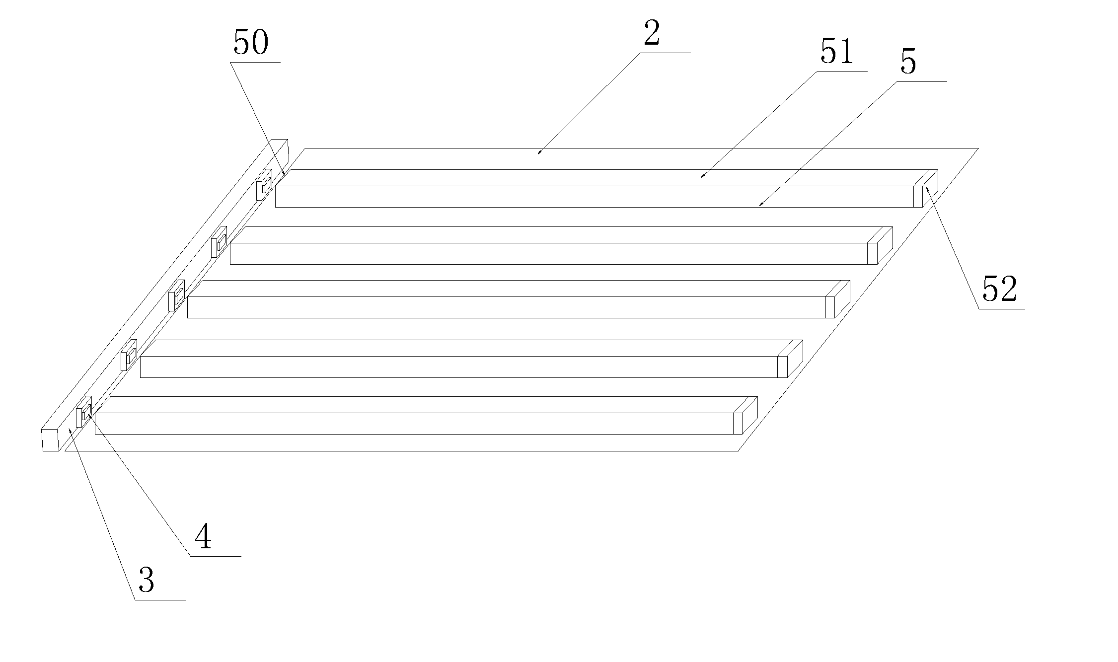
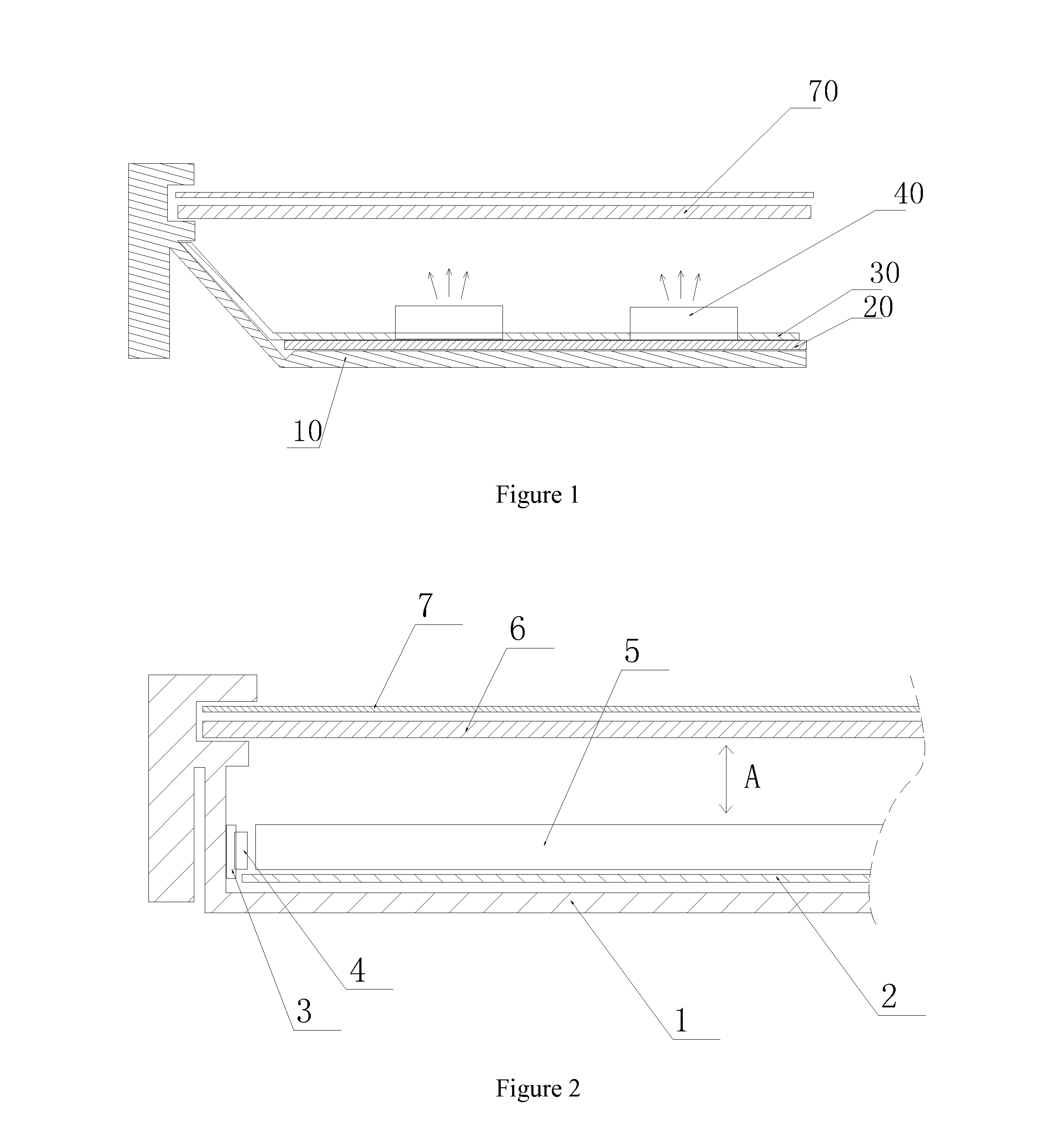
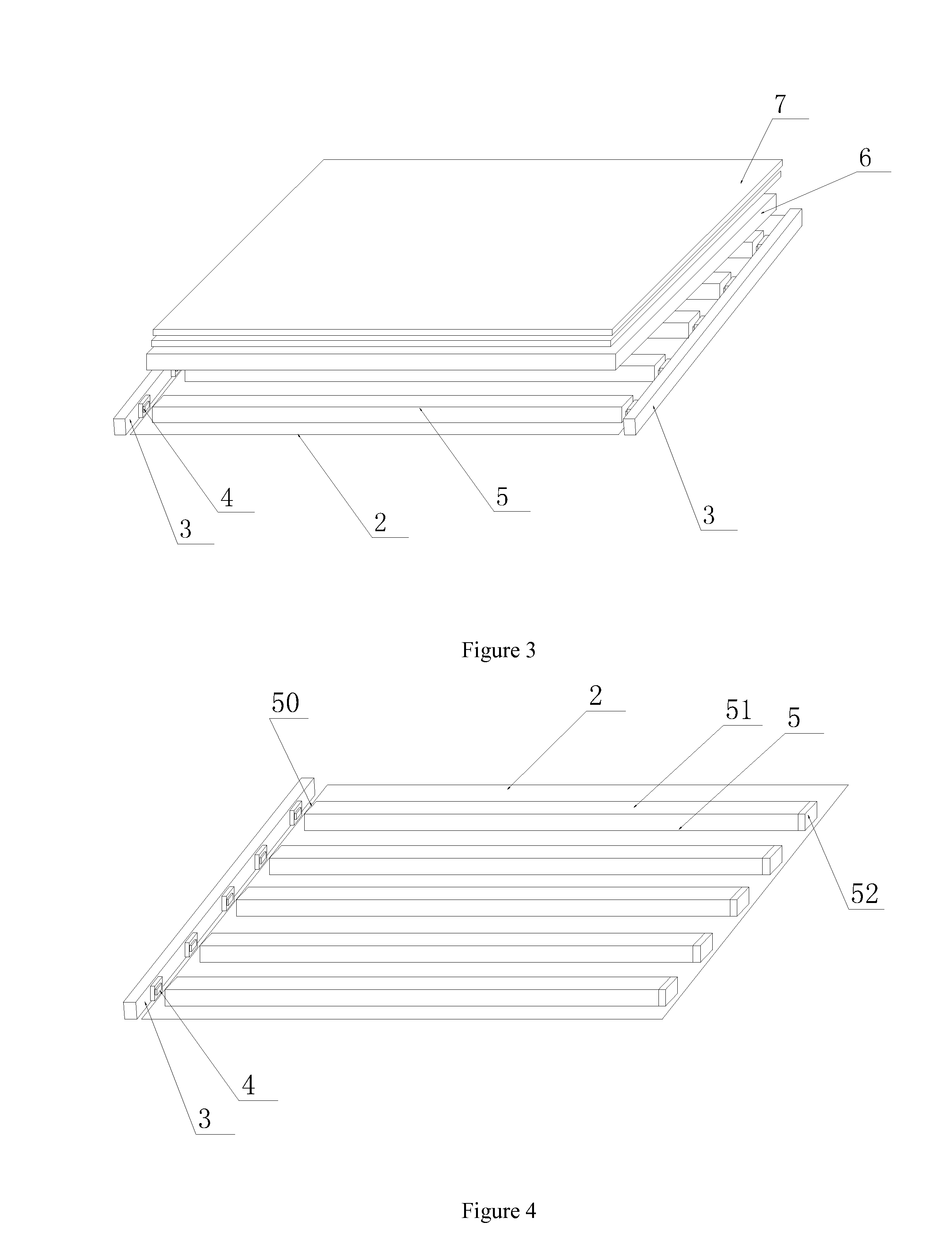
[0047]Referring to FIGS. 2 and 3, it shows a LED backlight module according to one embodiment of the present invention. In the LED backlight module according to the embodiment, it at least comprises:[0048]a backplane 1, the backplane 1 comprising a horizontal plate and at least one vertical plate extending from the horizontal plate;[0049]a side-type backlight source, which is provided on the inner wall of the vertical plate of the backplane 1, the side-type backlight source comprising a backlight source substrate 3 and multiple light emitting diodes provided on the backlight source substrate 3; wherein, the backlight source substrate 3 can be printed circuit board (PCB) fixed on the vertical plate of the backplane 1, and the incident light is emitted in either unilateral way or bilateral way; if it is emitted in bilateral way, the backplane 1 needs to having two vertical ...


PUM


Abstract

The present invention discloses a LED backlight module, which comprises a backplane; a side-type backlight source, which comprises a backlight source substrate and multiple light emitting diodes provided on the backlight light source substrate; a reflector, which is provided on the backplane; multiple light guides provided on the reflector in parallel, each light guide being provided with at least one light-incident surface and one light-emitting surface, the light-incident surface of the light guide being opposite to the LED; diffusers provided on the multiple light guides, which are opposite to the light-emitting surface of the light guide; and an optical film set, which is located above the diffuser. The embodiment of the present invention further discloses the corresponding liquid crystal display. According to the embodiment of the present invention, it can save the amount of LEDs, which is beneficial for the narrow frame of the liquid crystal display panel.

Description

[0001]This application claims priority to Chinese Patent Application Serial No. 201310466352.1, named as “LED backlight module and the corresponding liquid crystal display”, filed on Oct. 9, 2013, the specification of which is incorporated herein by reference.BACKGROUND OF THE INVENTION[0002]1. Field of the Invention[0003]The present invention relates to the structure of thin film transistor liquid crystal display (TFT-LCD), and in particular to a LED backlight module and the corresponding liquid crystal display.[0004]2. The Related Arts[0005]Among the existing technology, light emitting diode (LED) is commonly used as the light source of TFT-LCD backlight because it has the advantage of high energy efficiency.[0006]The schematic view illustrating the structure of the backlight module according to the prior art is shown in FIG. 1. The backlight module comprises: a backplane 10, a PCB plate 20 provided on the backplane 10, and a reflective plate 30. Wherein, multiple bottom lighting ...

Claims


Application Information

Patent Timeline
IPC IPC(8): F21V8/00
CPCG02B6/0075G02B6/0036G02B6/0051G02B6/0061
Inventor HE, HU
Owner TCL CHINA STAR OPTOELECTRONICS TECH CO LTD
Learn More