Elastically averaged alignment systems and methods

Active Publication Date: 2015-04-09
GM GLOBAL TECH OPERATIONS LLC
View PDF0 Cites 16 Cited by
  • Summary
  • Abstract
  • Description
  • Claims
  • Application Information

AI Technical Summary

Benefits of technology

[0004]In one aspect, an elastically averaged alignment system is provided. The alignment system includes a first component including at least one corner region having an alignment member, and a second component including at least one corner region having an inner wall defining an alignment aperture. The alignment aperture is configured to receive at least a portion of the alignment member to couple the first component and the second component. The alignment member is an elastically deformable material such that when the alignment member is inserted into the alignment aperture, the alignment member elastically deforms to an elastically averaged final configuration to facilitate aligning the corner regions of the first and second components in a desired orientation.
[0005]In another aspect, a vehicle is provided. The vehicle includes a body and an elastically averaged alignment system integrally arranged with the body. The elastically averaged alignment system includes a first component including at least one corner region having an alignment member, and a second component including at least one corner region having an inner wall defining an alignment aperture. The ali

Problems solved by technology

As a result, significant positional variation can occur between two mated components having the aforementioned alignment features, particularly at corner regions of the mated components, which may contribute to the presence of undesirably large variation in their alignment, particularly with regard to gaps and/or spacing therebetween.
In the case where misaligned components are also part of another assembly, such misalignments may also affect

Method used


Image

  • Elastically averaged alignment systems and methods
  • Elastically averaged alignment systems and methods
  • Elastically averaged alignment systems and methods

Examples


Example

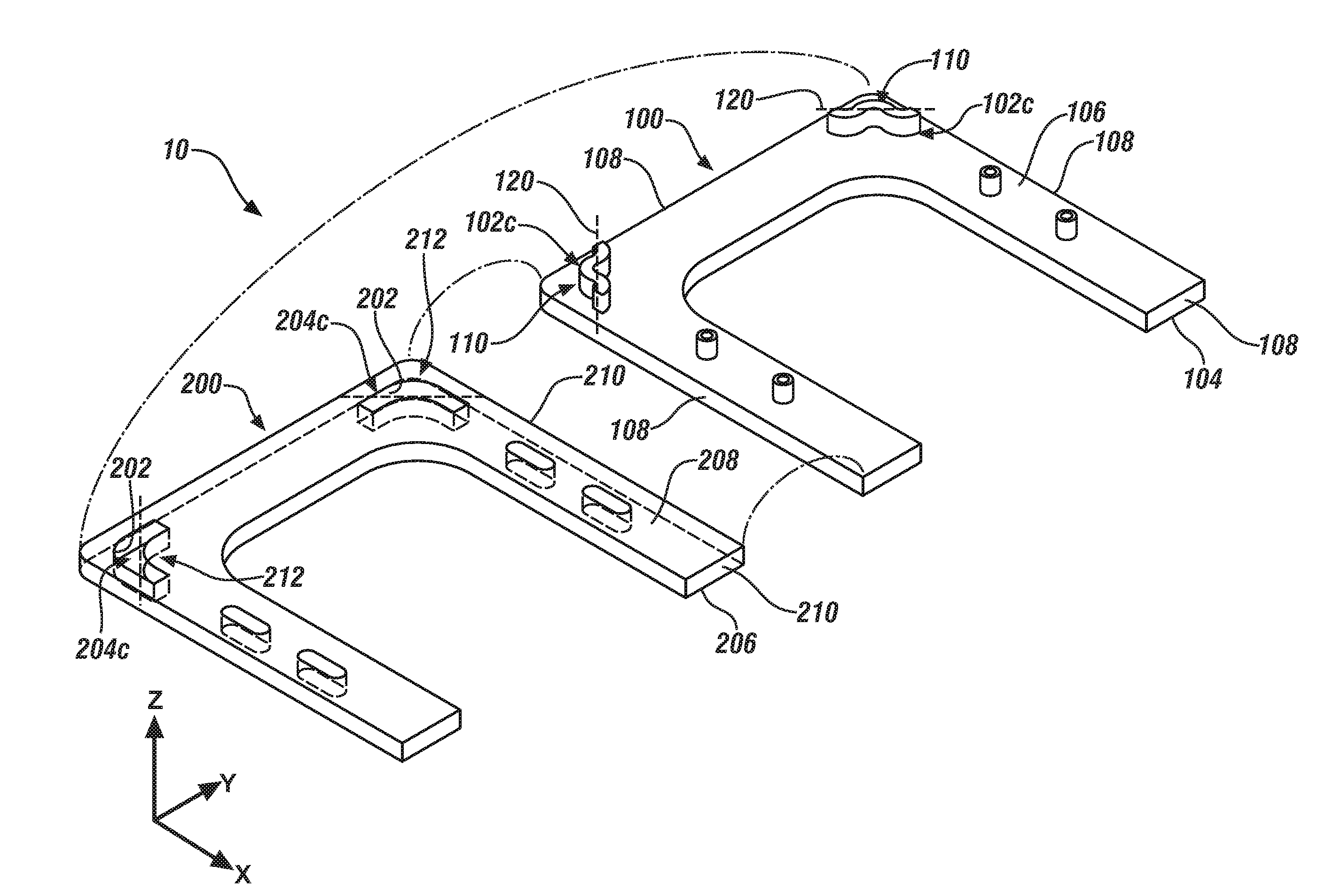
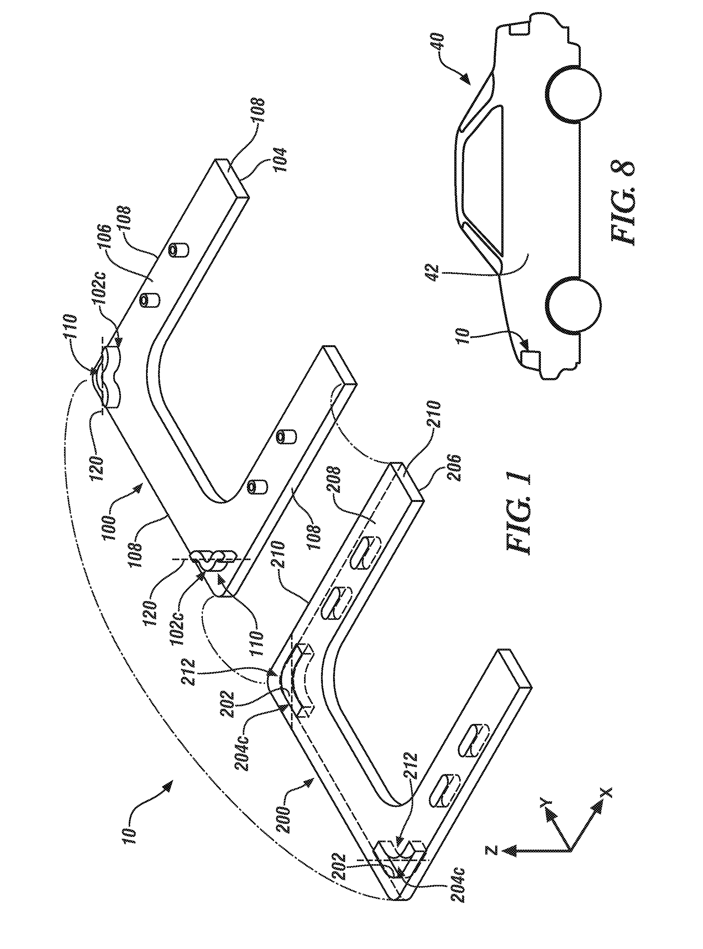
[0017]The following description is merely exemplary in nature and is not intended to limit the present disclosure, its application or uses. For example, the embodiments shown are applicable to vehicle body panels, but the alignment system disclosed herein may be used with any suitable components to provide elastic averaging for precision location and alignment of all manner of mating components and component applications, including many industrial, consumer product (e.g., consumer electronics, various appliances and the like), transportation, energy and aerospace applications, and particularly including many other types of vehicular components and applications, such as various interior, exterior and under hood vehicular components and applications. It should be understood that throughout the drawings, corresponding reference numerals indicate like or corresponding parts and features.

[0018]As used herein, the term “elastically deformable” refers to components, or portions of componen...


PUM

PropertyMeasurementUnit
Angleaaaaaaaaaa
Shapeaaaaaaaaaa
Waveaaaaaaaaaa

Abstract

In one aspect, an elastically averaged alignment system is provided. The alignment system includes a first component including at least one corner region having an alignment member, and a second component including at least one corner region having an inner wall defining an alignment aperture. The alignment aperture is configured to receive at least a portion of the alignment member to couple the first component and the second component. The alignment member is an elastically deformable material such that when the alignment member is inserted into the alignment aperture, the alignment member elastically deforms to an elastically averaged final configuration to facilitate aligning the corner regions of the first and second components in a desired orientation.

Description

FIELD OF THE INVENTION[0001]The subject invention relates to matable components, and more specifically, to elastically averaged matable components.BACKGROUND[0002]Components, in particular vehicular components, which are to be mated together in a manufacturing process, are mutually located with respect to each other by alignment features that are oversized holes and / or undersized upstanding bosses. Such alignment features are sized to provide spacing to freely move the components relative to one another to align them without creating an interference therebetween that would hinder the manufacturing process. One such example includes two-way and / or four-way male alignment features, typically upstanding bosses, which are received into corresponding female alignment features, typically apertures in the form of slots or holes. The components are formed with a predetermined clearance between the male alignment features and their respective female alignment features to match anticipated si...

Claims


Application Information

Patent Timeline
IPC IPC(8): B62D27/02B62D27/06
CPCB62D27/06B62D27/02F16F15/04B60R13/00F16B19/004Y10T403/1616Y10T29/49945
Inventor MORRIS, STEVEN E.LAWALL, JENNIFER P.
Owner GM GLOBAL TECH OPERATIONS LLC
Why Eureka
Try Eureka