Aircraft fluid gauging techniques using pressure measurements and optical sensors

a technology of optical sensors and pressure measurements, applied in liquid/fluent solid measurement, instruments, machines/engines, etc., can solve the problems of complex protection mechanisms, large number of in-tank electrical wires, and significant system weigh

Inactive Publication Date: 2015-04-09
PARKER HANNIFIN CORP
View PDF11 Cites 37 Cited by
  • Summary
  • Abstract
  • Description
  • Claims
  • Application Information

AI Technical Summary

Problems solved by technology

In order to provide adequate system accuracy (usually expressed as the total mass of fuel in a tank), many of these probes are required, resulting in a significant system weight (e.g., due to the probes themselves and their associated electrical wiring).
In addition, capacitive probes are sensitive to electrically conductive contaminants in the fuel (including water) and the large number of in-tank electrical wires presents an intrinsic safety hazard, requiring complex protection mechanisms.
Pressure sensors are also insensitive to electrically-conductive contaminants in the fuel, and do not have the same height measurement limits as capacitive probes.
In the past, commercially available pressure sensors did not have the required resolution and accuracy over the required full-scale range of pressure (down to a few thousandths of a PSI or a few milliPSI over a full-scale range of tens of PSI) needed for reasonable system accuracy.

Method used


Image

  • Aircraft fluid gauging techniques using pressure measurements and optical sensors
  • Aircraft fluid gauging techniques using pressure measurements and optical sensors
  • Aircraft fluid gauging techniques using pressure measurements and optical sensors

Examples


Embodiment Construction

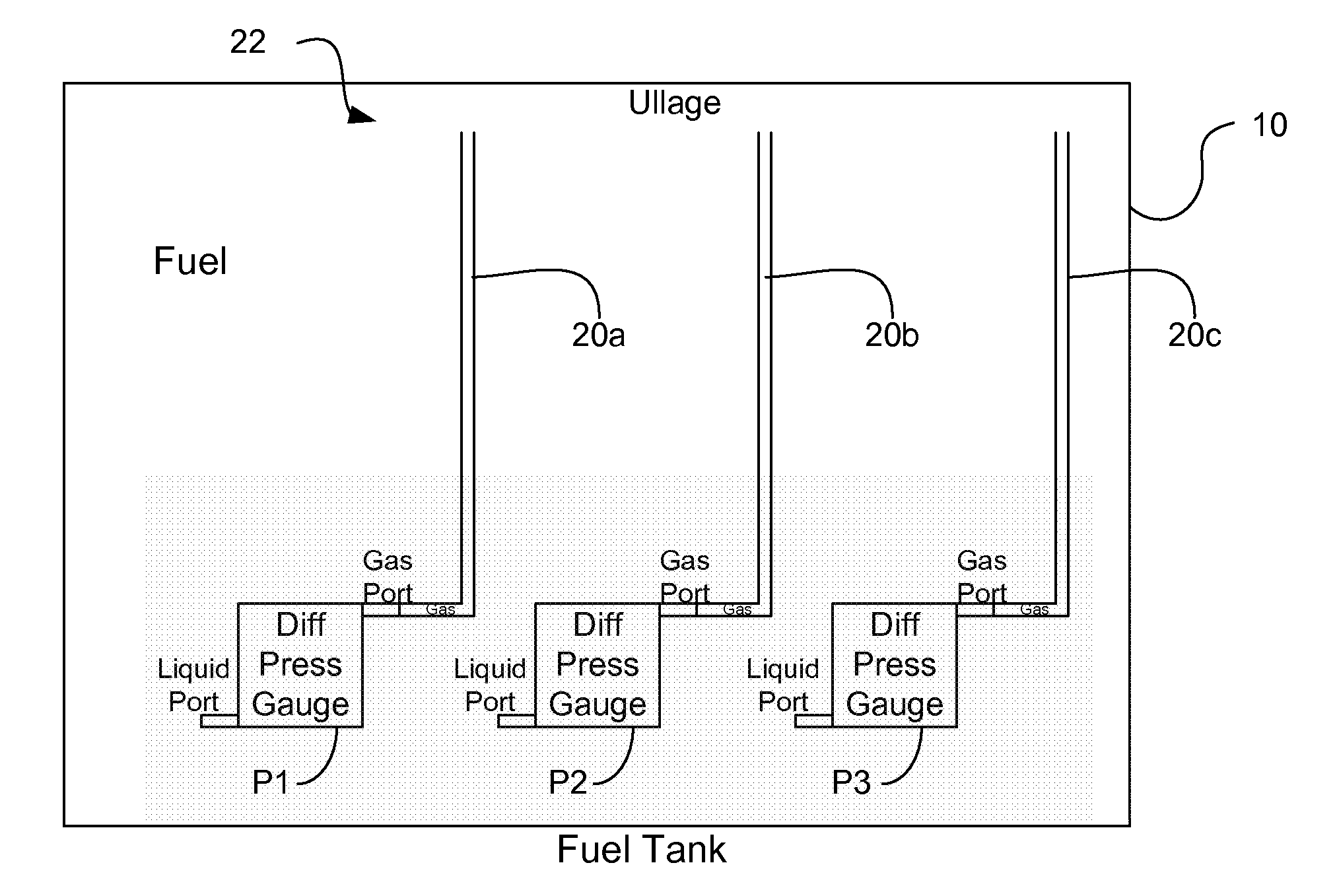
[0048]The present invention will be described in the context of a fuel tank of a vehicle, such as an aircraft. However, such description is intended to be exemplary, and those having ordinary skill in the art will appreciate that aspects of the present invention may be applied to fuel tanks for other vehicles and / or to other containers that store a fluid.

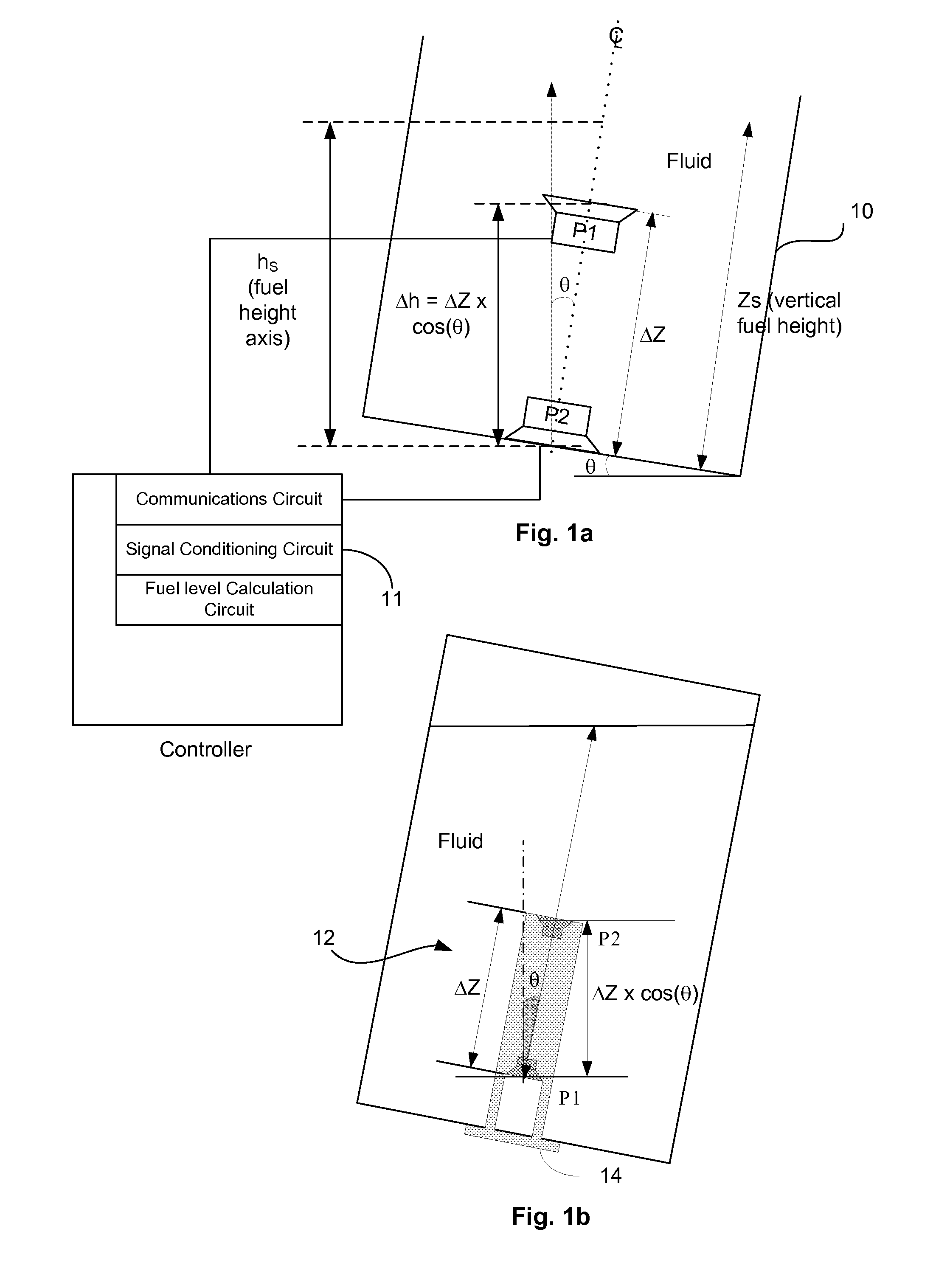
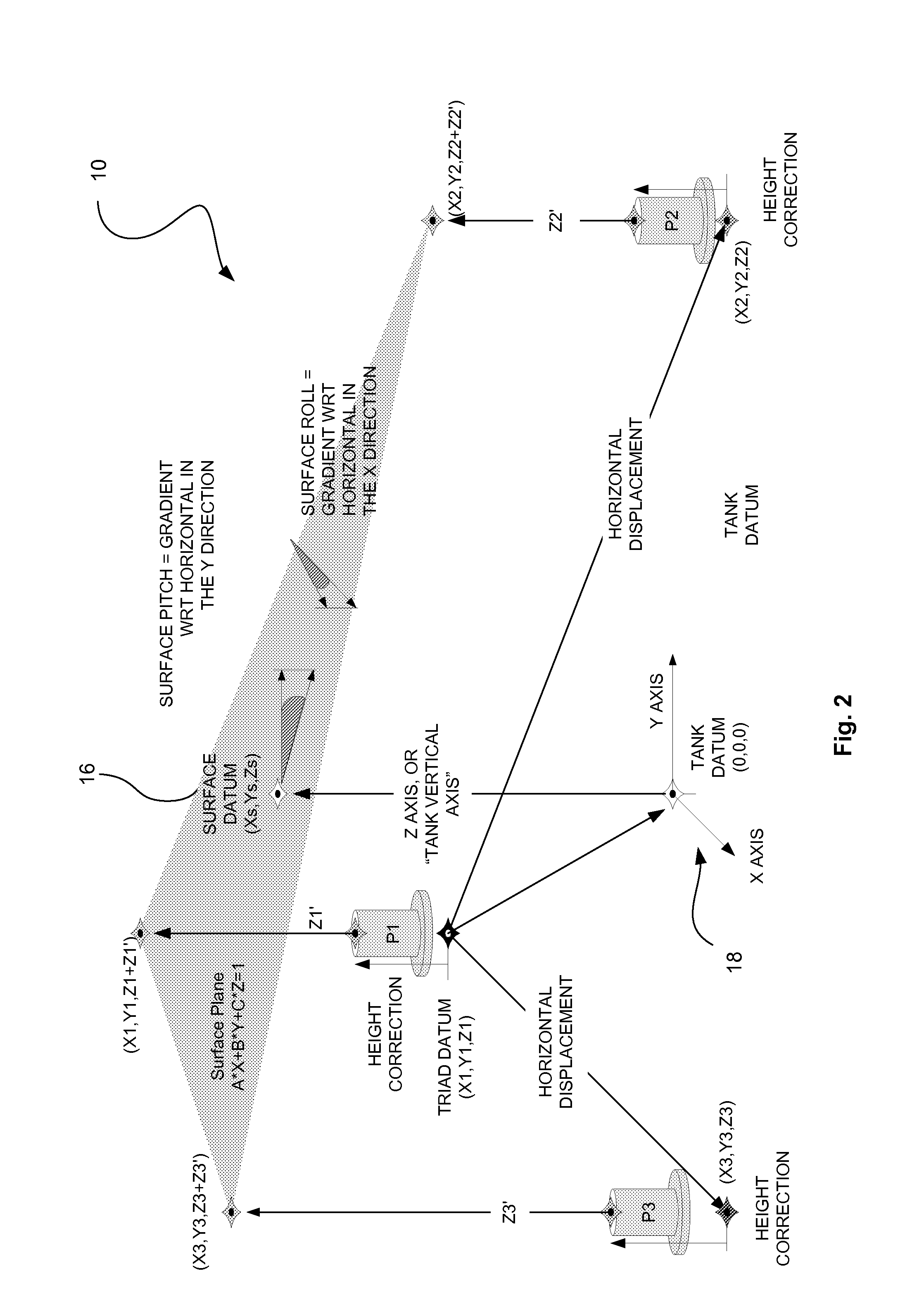
[0049]As used herein, the term “height axis” refers to an axis that is generally parallel with an axis defined by dominant gravitational forces exerted on the fluid tank and perpendicular to a fluid surface. For example, a tank may have a first “fixed” axis, which may be referred to as a tank vertical axis (e.g., Z in FIG. 2), while a location of the height axis (e.g., h in FIG. 1a) may move relative to the tank vertical axis depending on the orientation of the tank.

[0050]The mass of fuel in a tank can be determined from the fuel volume (V) and the fuel density (ρ). For example, the fuel mass, m, can be determined using Equation 1.

m...


PUM

PropertyMeasurementUnit
heightaaaaaaaaaa
pressureaaaaaaaaaa
pressuresaaaaaaaaaa

Abstract

A fluid level measurement system includes a first pressure sensor disposed inside a fluid tank at a first elevation relative to a height axis of the fluid tank, and a second pressure sensor disposed inside the fluid tank at a second elevation relative to the height axis of the fluid tank, the second elevation different from the first elevation. The first pressure sensor and the second pressure sensor are configured to provide a signal indicative of a sensed pressure, and fluid height is calculated from the difference in sensed pressure between the first and second pressure sensors relative to the sensed pressure of either the first or the second pressure sensor.

Description

RELATED APPLICATION DATA[0001]This application claims the priority of U.S. Provisional Application No. 61 / 888,572, filed on Oct. 9, 2013, which is hereby incorporated in its entirety by reference.TECHNICAL FIELD[0002]The present application relates generally to fluid gauging and, more particularly, to a system, apparatus and method for using pressure measurements to gauge fluid levels in a fluid tank.BACKGROUND ART[0003]The majority of aircraft fluid level gauging systems such as, for example, fuel tank level gauging systems, rely upon capacitance-based probes as their primary sensors. In order to provide adequate system accuracy (usually expressed as the total mass of fuel in a tank), many of these probes are required, resulting in a significant system weight (e.g., due to the probes themselves and their associated electrical wiring). In addition, capacitive probes are sensitive to electrically conductive contaminants in the fuel (including water) and the large number of in-tank el...

Claims


Application Information

Patent Timeline
Patent Type & Authority Applications(United States)
IPC IPC(8): G01F23/14G01L11/02
CPCG01L11/02G01F23/14G01F22/00G01F23/18
Inventor AUSTERLITZ, HOWARD P.BUETER, RONALD W.WOOD, STANLEYBOYD, LEWIS J.
Owner PARKER HANNIFIN CORP
Why Eureka
Try Eureka