
Electroosmotic pump unit and assembly

a technology of electroosmotic pump and assembly, which is applied in the direction of machines/engines, liquid/fluent solid measurement, peptides, etc., can solve the problem that few existing micropumps can produce adequate pumping pressure for loc hplc applications

Inactive Publication Date: 2015-04-16
THE BOARD OF RGT UNIV OF OKLAHOMA
View PDF13 Cites 5 Cited by
  • Summary
  • Abstract
  • Description
  • Claims
  • Application Information

AI Technical Summary

Benefits of technology

This patent describes a new type of pump called an electroosmotic pump that can generate high-pressures for use in high-performance liquid chromatographic (HPLC) systems. These pumps are promising because they can be integrated into lab-on-a-chip platforms, which are useful for analyzing samples at the point of need. The patent also describes a method for manufacturing these pumps and the results of a study that shows the relationship between pressure output and the number of pumps used. The technical effects of this patent are the development of a more powerful and efficient pump for HPLC applications and the ability to integrate it into smaller devices for use in research and drug discovery.

Problems solved by technology

Currently, few existing micropumps can produce adequate pumping pressure for LOC HPLC applications.
However, due to the typical pressures used in HPLC separations, multiple open capillaries have to be utilized in parallel to produce adequate flow to drive HPLC separations.

Method used


Image

  • Electroosmotic pump unit and assembly
  • Electroosmotic pump unit and assembly
  • Electroosmotic pump unit and assembly

Examples


example

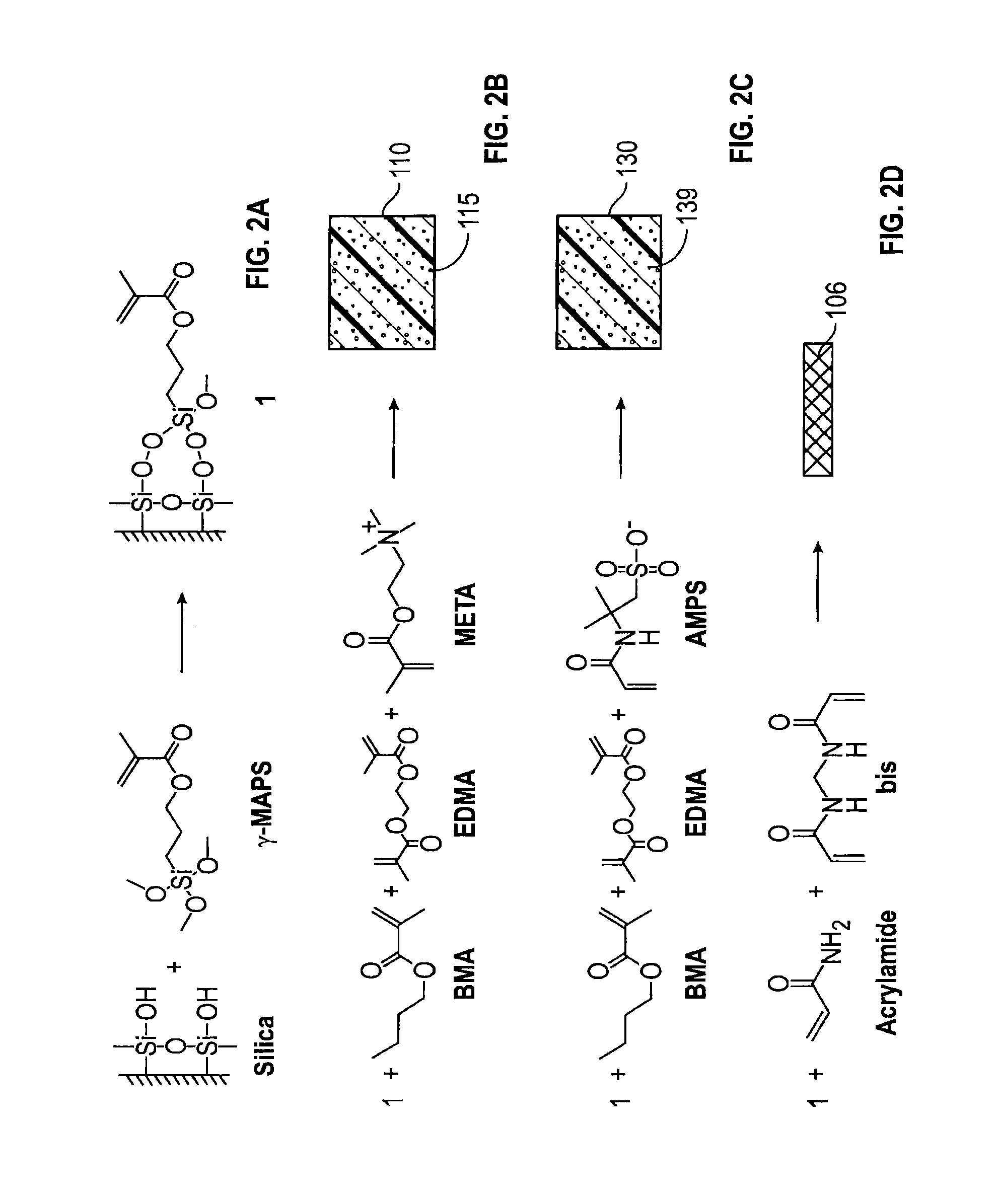
[0131]This example describes a non-limiting embodiment of a high-pressure EOP constructed in accordance with the presently disclosed inventive concepts. In this embodiment, the monolith material has been improved by applying a pressure to the monomer solution during polymerization. A binary (i.e., double monolith) EOP gradient generator (“bi-Egg”) is assembled, and the relationship between the gradient profile and voltage applied on the EOP is examined. The feasibility of the binary EOP gradient generator for generating smooth and reproducible nanoflow gradient is demonstrated. After integrating the gradient generator into a miniaturized HPLC, the HPLC is used for separating peptide mixtures from trypsin-digested proteins. The performance of the miniaturized HPLC assembly constructed herein is compared to that of a commercially-available HPLC (an Agilent 1200 HPLC). The two devices exhibit comparable efficiencies, resolutions, and peak capacities.


PUM

PropertyMeasurementUnit
Pore sizeaaaaaaaaaa
Pore sizeaaaaaaaaaa
Sizeaaaaaaaaaa

Abstract

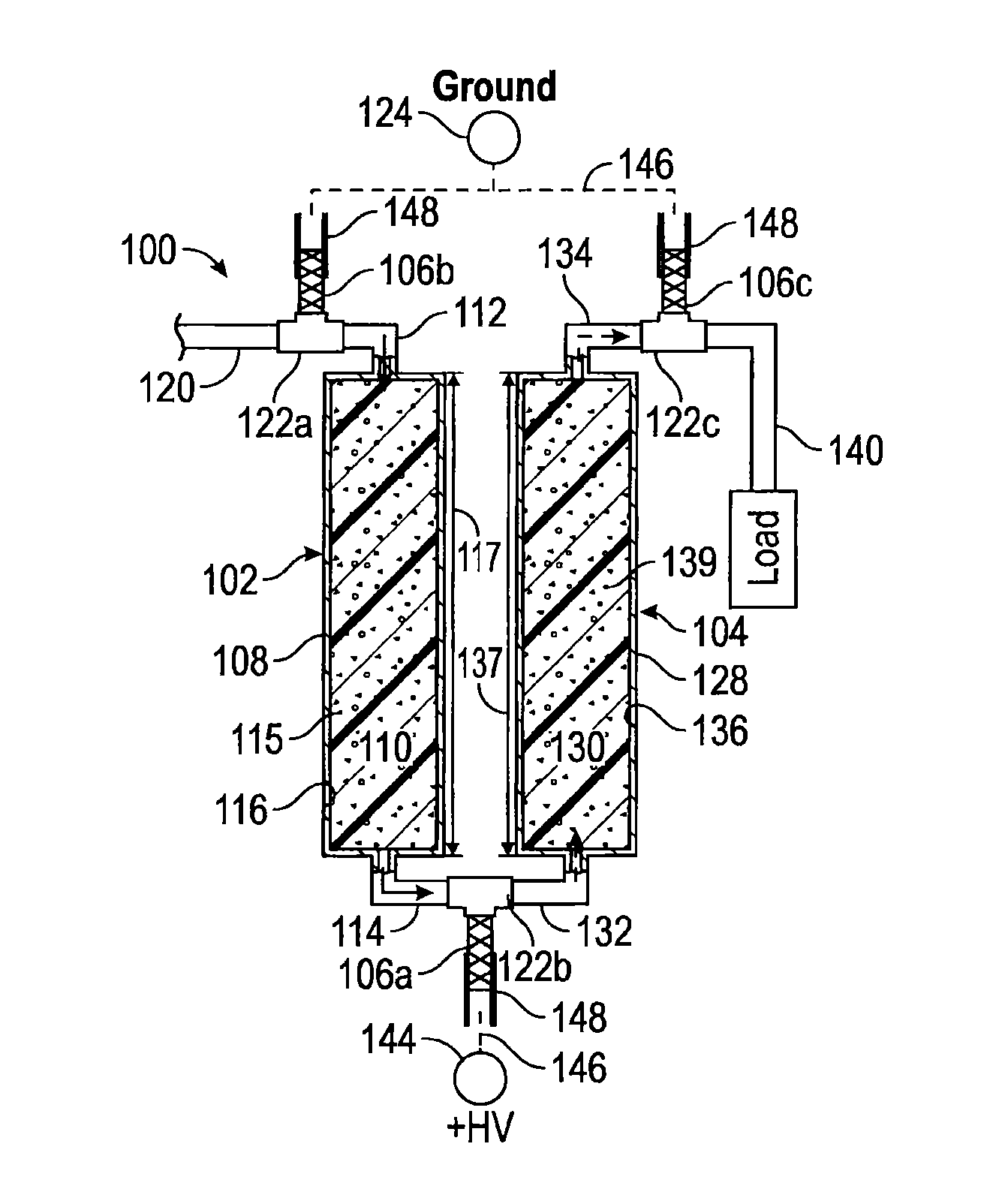
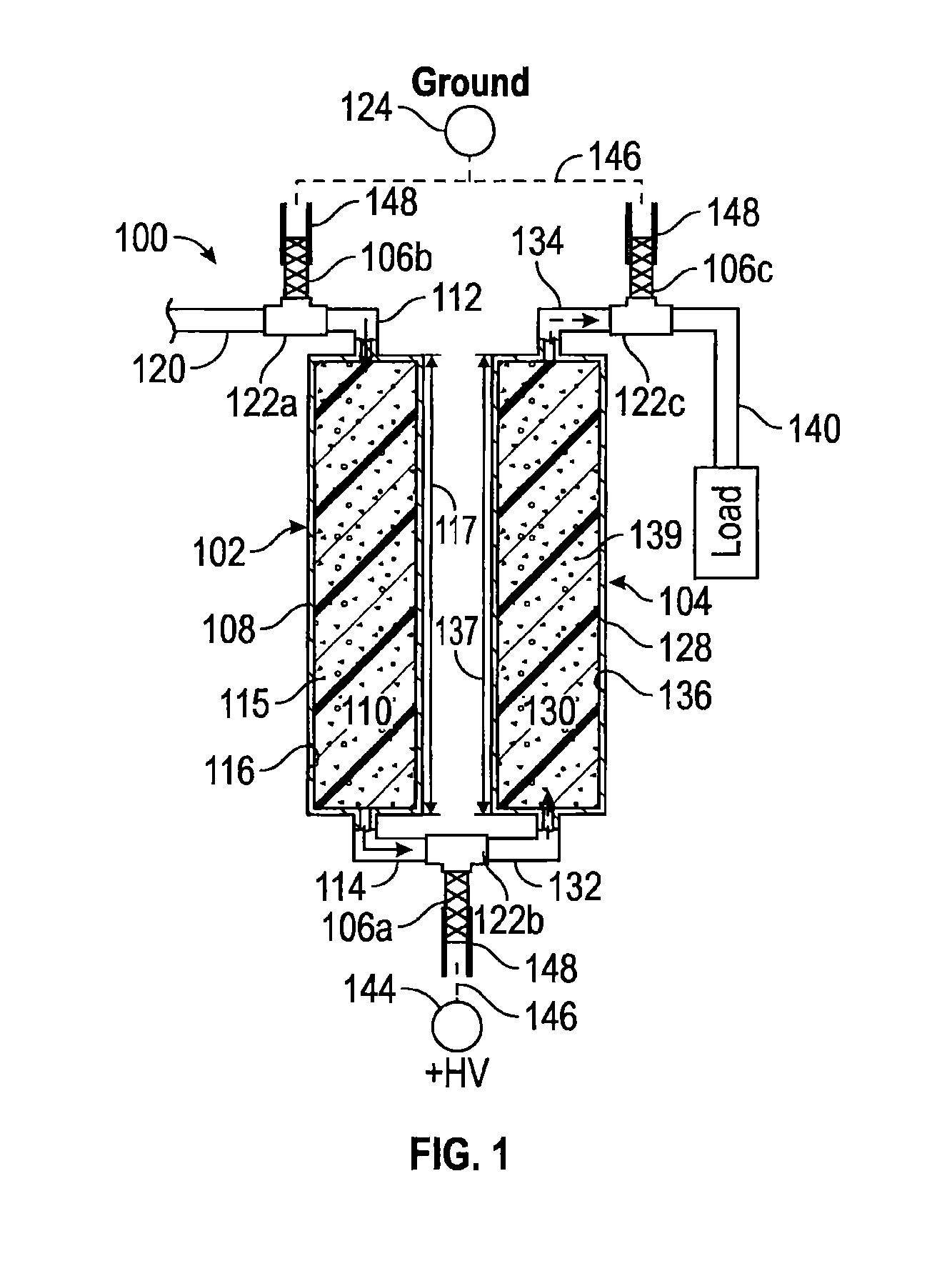
An electroosmotic pump unit includes at least a first pump element, at least a second pump element, and an electrode. Each pump element includes a tube, an electrically grounded fluid inlet, a fluid outlet electrically coupled to the electrode, and a porous monolith immobilized in the tube and having open pores having net surface charges. When the electrode applies a voltage across the monoliths, a fluid supplied to the first pump element flows through the pump elements in a direction from a fluid inlet of the first pump element toward a fluid outlet of the second pump element. A plurality of electroosmotic pump units may be connected in series in a pump assembly. The electroosmotic pump unit, or pump assembly, may be connected to an apparatus such as a HPLC.

Description

CROSS REFERENCE TO RELATED APPLICATIONS[0001]This application claims priority to U.S. Provisional Application Ser. No. 61 / 889,897, filed Oct. 11, 2013, the entire content of which is hereby expressly incorporated herein by reference.STATEMENT REGARDING FEDERALLY SPONSORED RESEARCH OR DEVELOPMENT[0002]This invention was supported by Department of Energy under DE-SC0006351, and the National Science Foundation under CHE-1011957. The United States government has certain rights in this invention.BACKGROUND[0003]The ability of micropumps to generate high-pressures is appealing because it enables integration of a complete high performance liquid chromatographic (HPLC) system on a lab-on-a-chip (LOC) platform. HPLC is arguably the most commonly utilized separation technique for chemical analysis. HPLC can analyze 80% of all known compounds and it is widely used from drug compound screening to medicine production, from clinical diagnosis to food quality examination, and from environmental pr...

Claims


Application Information

Patent Timeline
IPC IPC(8): F04B19/00F04B19/04
CPCF04B19/006F04B19/04B01D61/4271
Inventor LIU, SHAORONG
Owner THE BOARD OF RGT UNIV OF OKLAHOMA
Learn More