Wire harness fixture and method of producing wire harness with fixture having wire harness fixture attached thereto

Inactive Publication Date: 2015-04-16
SUMITOMO WIRING SYST LTD
View PDF14 Cites 5 Cited by
  • Summary
  • Abstract
  • Description
  • Claims
  • Application Information

AI Technical Summary

Benefits of technology

This patent provides a wire harness fixture that allows for differentiation between a center type and an offset type. The fixture includes a base with a clip, a winding band, and engagement portions. A first band insertion hole is provided in the base and a second band insertion hole is provided in the clip and base. This allows for positioning the center axis of the clip through the wire harness. The wire harness fixture also prevents misassembly and interference with the wire harness when using the offset type.

Problems solved by technology

However, in a case where an obstacle is located proximate to the attachment portion of the wire harness fixture or where the wire harness is too thick, the center-type wire harness fixture may cause a problem with attachment.
Such a method, however, requires preparation of two types of wire harness fixtures (center type and offset type) having different wire harness assembly positions, thus leading to an increase in the number of components and the cost.
This makes misassembly of the center type and offset type extremely difficult to prevent.
Thus, a cutter cutting the fore end portion of the winding band after the wire harness is fixated may interfere with the wire harness.
This is not an ideal solution.

Method used


Image

  • Wire harness fixture and method of producing wire harness with fixture having wire harness fixture attached thereto
  • Wire harness fixture and method of producing wire harness with fixture having wire harness fixture attached thereto
  • Wire harness fixture and method of producing wire harness with fixture having wire harness fixture attached thereto

Examples


Embodiment Construction

[0033]The particulars shown herein are by way of example and for purposes of illustrative discussion of the embodiments of the present invention only and are presented in the cause of providing what is believed to be the most useful and readily understood description of the principles and conceptual aspects of the present invention. In this regard, no attempt is made to show structural details of the present invention in more detail than is necessary for the fundamental understanding of the present invention, the description taken with the drawings making apparent to those skilled in the art how the forms of the present invention may be embodied in practice.

[0034]Embodiments of the present invention are described below with reference to the drawings.

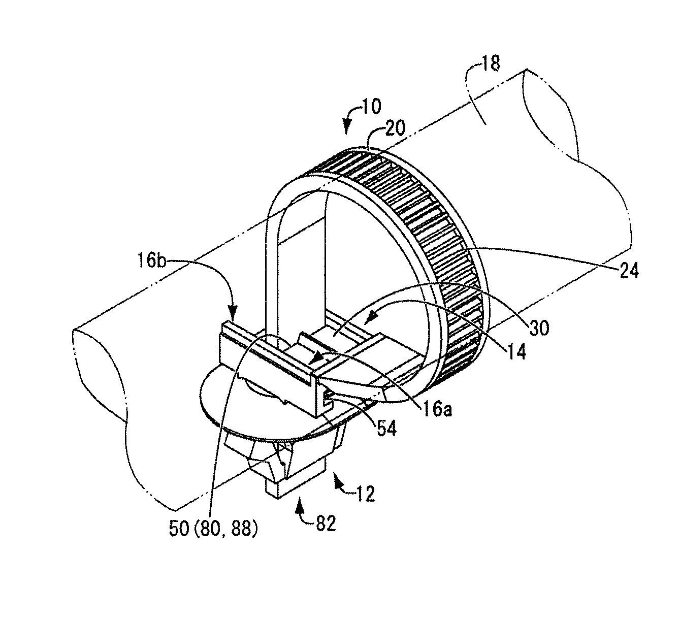
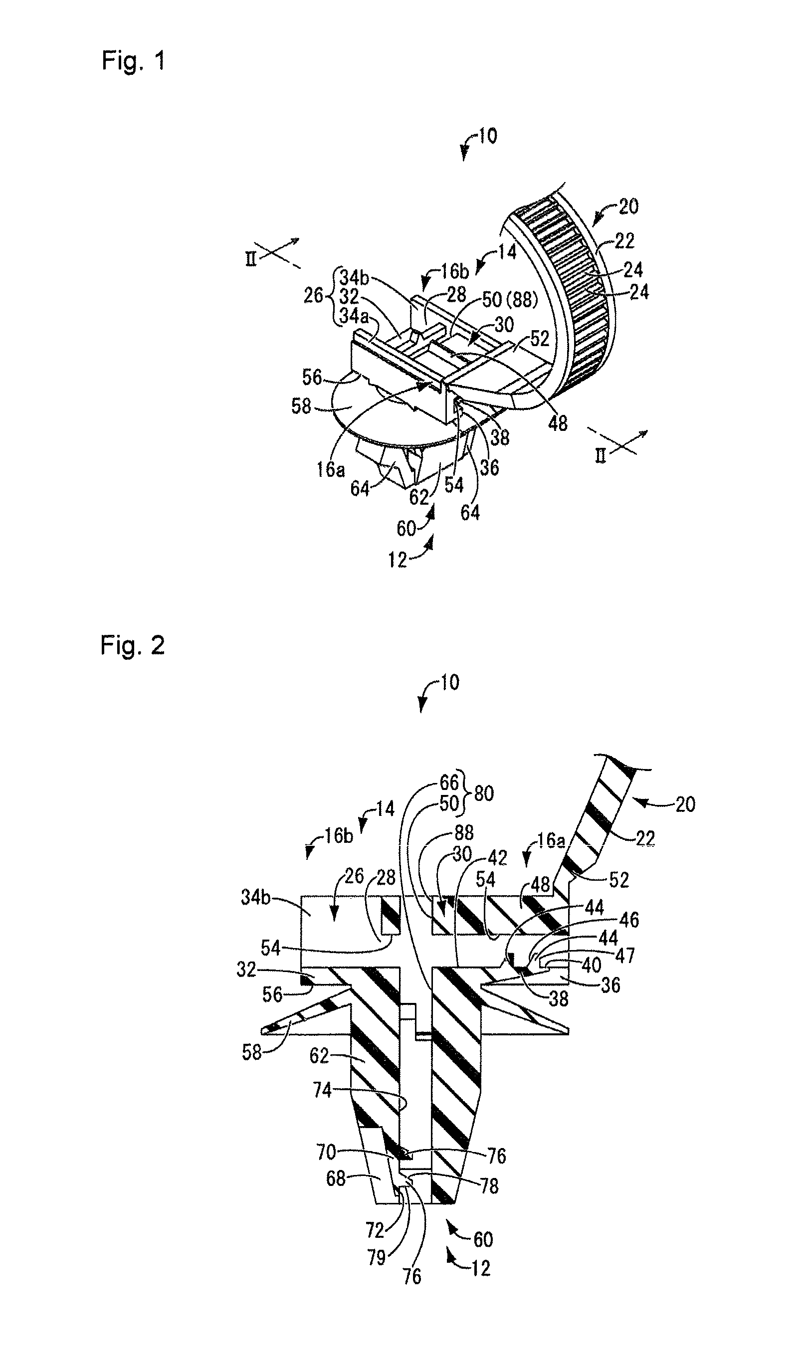
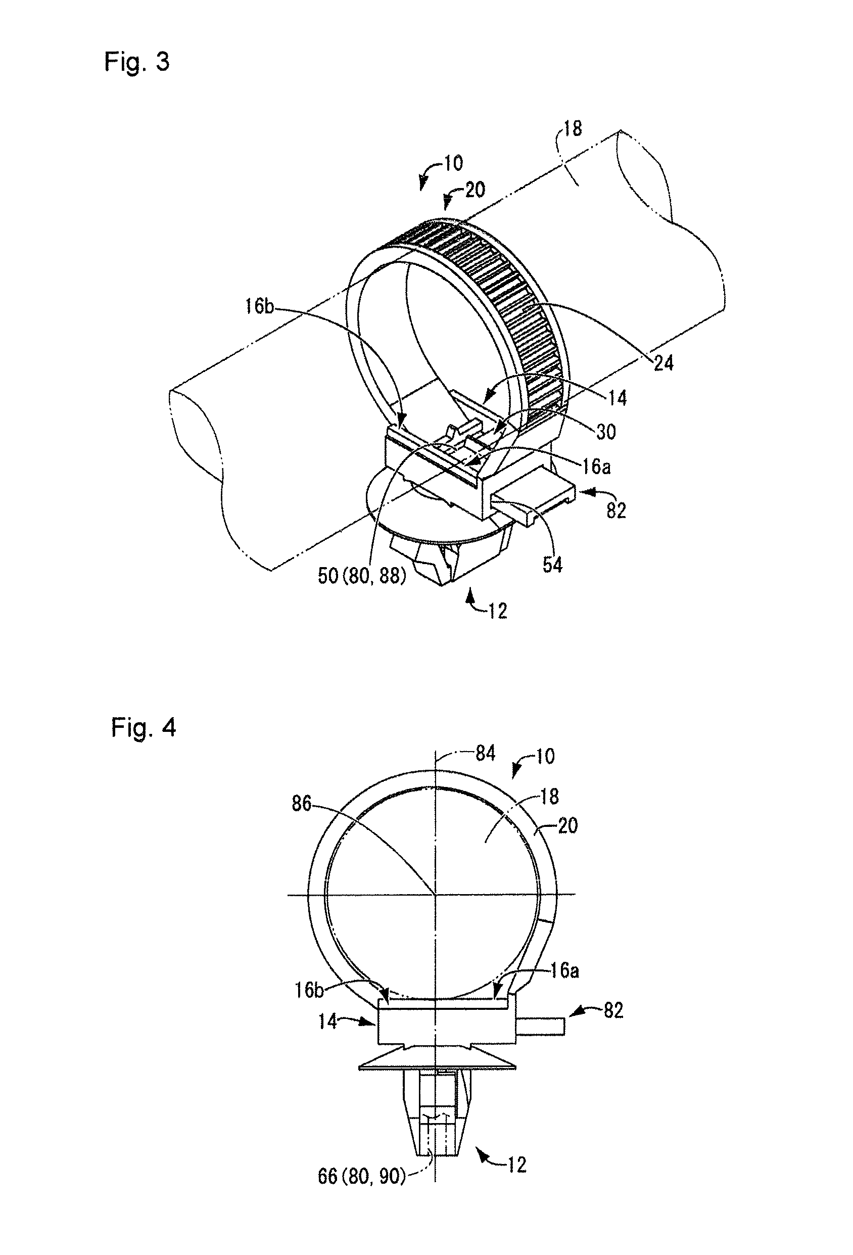
[0035]FIGS. 1 and 2 each illustrate a wire harness fixture 10 according to an embodiment of the present invention. With reference to FIG. 1, the wire harness fixture 10 includes a base 14 from which a clip 12 projects, and a winding band...


PUM


Abstract

A wire harness fixture includes a base having a clip projecting therefrom; a winding band extending and winding around a wire harness from a first end portion of two end portions of the base; and a plurality of engagement portions on a surface of the winding band. The base has a first band insertion hole passing through the two end portions of the base in a direction orthogonal to a projecting direction of the clip, the first band insertion hole having a first engagement projection engaging with the engagement portions of the winding band. The clip and the base have a second band insertion hole passing therethrough in the projecting direction of the clip, the second band insertion hole having a second engagement projection engaging with the engagement portions of the winding band.

Description

CROSS-REFERENCE TO RELATED APPLICATIONS[0001]The present application claims priority under 35 U.S.C. §119 of Japanese Application No. 2013-212408, filed on Oct. 10, 2013, the disclosure of which is expressly incorporated by reference herein in its entirety.BACKGROUND OF THE INVENTION[0002]1. Field of the Invention[0003]The present invention relates to a wire harness fixture attached to an outer periphery of a wire harness such that a projecting clip is fixated to an attachment portion of a vehicle body panel or a vehicle device. The present invention also relates to a method of producing a wire harness with a fixture having the wire harness fixture attached thereto.[0004]2. Description of Related Art[0005]A wire harness fixture is conventionally used to fixate a wire harness routed in a vehicle to an attachment portion of a vehicle body panel or a vehicle device. As disclosed in Japanese Patent Laid-Open Publication No. H8-275346, such a wire harness fixture is integrally provided w...

Claims


Application Information

Patent Timeline
IPC IPC(8): B60R16/02F16L3/12
CPCB60R16/0215F16L3/1211F16B2/08F16B5/0685Y10T29/49838
Inventor YAMAGUCHI, YOSHIHISA
Owner SUMITOMO WIRING SYST LTD
Why Eureka
Try Eureka