Device for cyclic spreading of tray sealing film in sealing machines

Active Publication Date: 2015-04-23
GRUPPO FABBRI VIGNOLA
View PDF3 Cites 3 Cited by
  • Summary
  • Abstract
  • Description
  • Claims
  • Application Information

AI Technical Summary

Benefits of technology

[0006]These documents do not suggest how it is possible to solve the technical problem at the basis of the invention, reducing consumption of the film in the tray sealers, reducing to the minimum possible advance of said film between the subsequent cycles of these machines, even if the off-cut of film remains in cooperation with the spreader, with a device according to claim 1 and the subsequent dependent claims, which envisages downstream heat-sealing and cutting bells, pincer means which, in step with closure of said bells, close on the longitudinal edges of the film just

Problems solved by technology

This solution only gives the desired results if the film is advanced until it touches the spreader with an uncut section of it, i.e. until the entire off-c

Method used


Image

  • Device for cyclic spreading of tray sealing film in sealing machines
  • Device for cyclic spreading of tray sealing film in sealing machines

Examples


Embodiment Construction

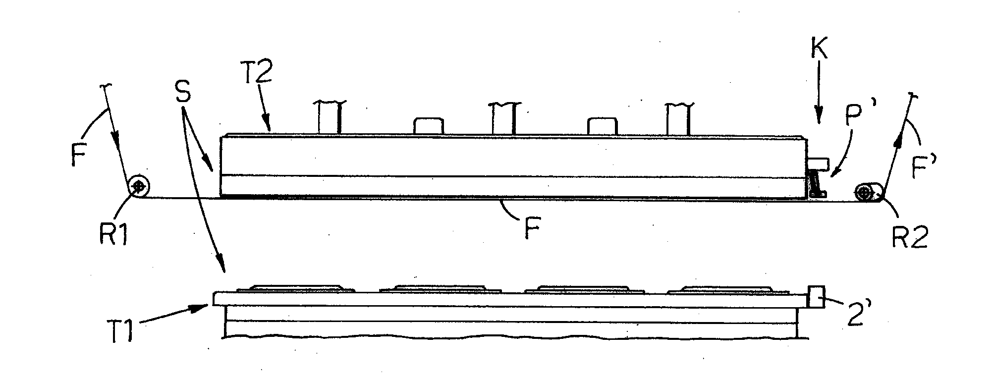
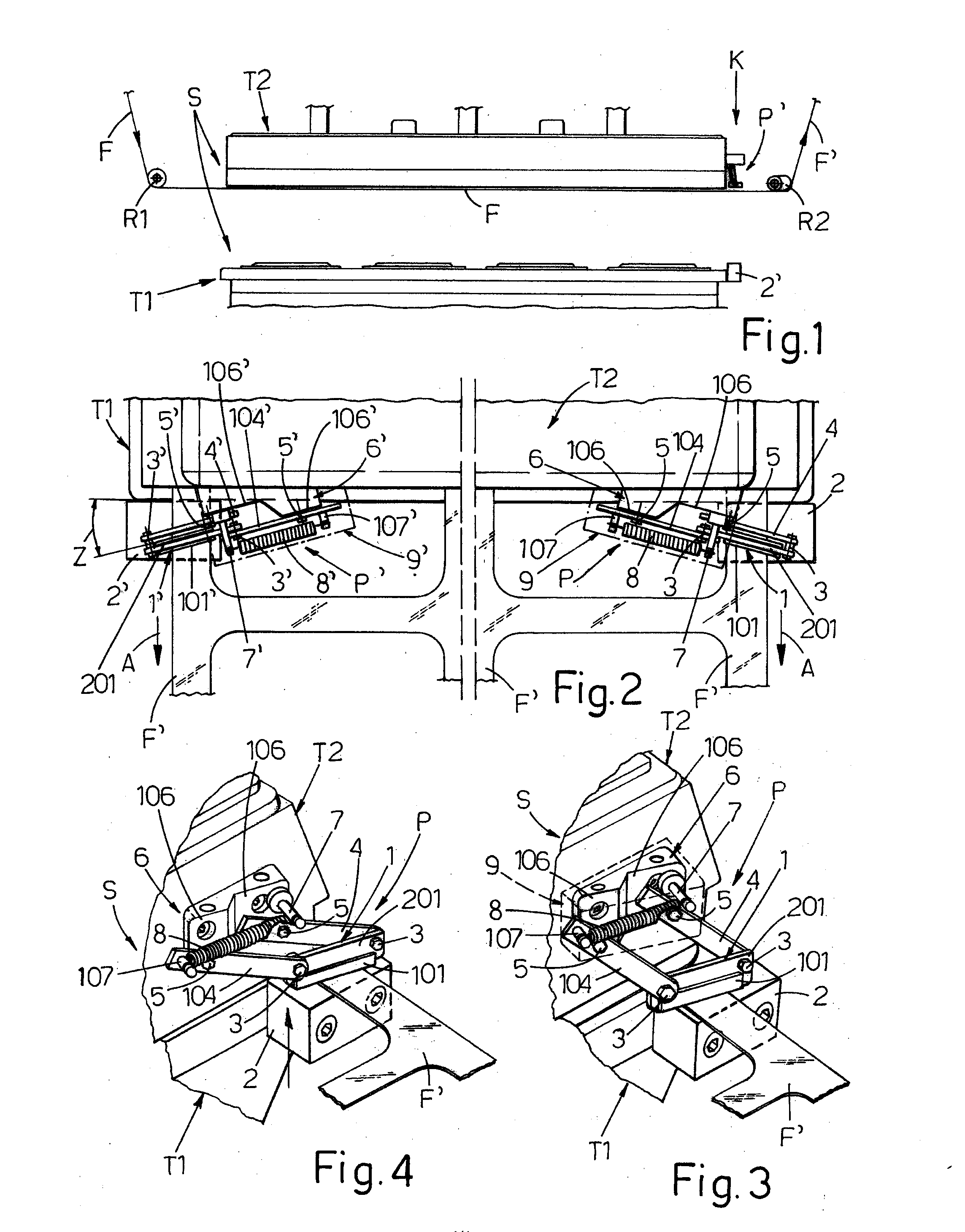
[0011]In FIG. 1, the letter S denotes the sealing and cutting station of a tray sealer, with the lower bell T1 on which pincer means (not shown) cyclically position an ordered set of trays (also not shown), and which in the idle position is lowered and duly distanced from an upper bell T2 which, as said, contains the sealing and cutting means, which is mounted statically on a supporting frame and beneath which film F transits and is arranged at a short distance, coming from the left, from a supply reel (not shown) and from return onto an idle roller R1, and which, on the right of station S, is returned onto the spreader roller R2 and which, in the form of off-cut F′, is connected to a collection beam (also not shown). The lower bell T1 is mounted on raising and lowering means and, after being loaded with trays, it is lifted to house said trays in their own slots and to close package-style beneath bell T2, gripping the interposed section of film F, which is sealed and cut around the ...


PUM


Abstract

A device for spreading the tray sealing film in so-called tray sealers, in order to avoid the formation of folds in said film (F) which, with the trays, is inserted in a sealing and cutting station (S), between a pair of opposing bells (T1, T2) provided with a relative reciprocal approaching and distancing movement, where downstream of said station (S) means are provided to subject the off-cut of film which exits to a transversal stretching action which ensures correct spreading of said film between said bells, characterized by comprising means for braking the film upstream of said station (S) and comprising pincer means (P, P′) with a jaw (1, 1′) mounted on the side of the upper bell (T2) from which the film exits, turned downwards and vertically opposing a corresponding jaw (2, 2′) mounted on the lower bell (T1), all being envisaged to ensure that in the reciprocal approach and closure step of the two bells (T1, T2), before the film is gripped and blocked between them, longitudinal and lateral portions of the film (F, F′) which are close to the bells are pincered between said opposing pairs of jaws (1, 2, 1′, 2′) of said pincers (P, P′), which firmly grip the film, also due to the presence of counter springs (8, 8′) and friction sliding blocks (101, 101′) and which, due to an inclines and divergent position of them with respect to the direction (A) of advance of the film, subject said film to transversal or preferably transversal and longitudinal stretching, in the same direction of advance (A) indicated above, to spread the film between the bells before their closure on said film.

Description

CROSS REFERENCE TO RELATED APPLICATIONS[0001]The present application claims priority to PCT International Application No. PCT / EP2013 / 060240 filed on May 17, 2013, which claims priority to Italian Patent Application No. B02012A000283 filed May 24, 2012, the entirety of the disclosures of which are expressly incorporated herein by reference.STATEMENT RE: FEDERALLY SPONSORED RESEARCH / DEVELOPMENT[0002]Not Applicable.BACKGROUND OF THE INVENTION[0003]The invention relates to the so-called tray sealers, i.e. machines which seal with a covering film tubs or trays filled with a product to be packaged, such as a food product. The document cited as the closest prior art to this invention is the published U.S. patent application No. US 2004 / 098947, which envisages placing downstream of the sealing and cutting station a pair of complementary-shaped rollers which are used to pincer the longitudinal edges of the film exiting from said station, which are divergent to each other in the direction of ...

Claims


Application Information

Patent Timeline
IPC IPC(8): B65B7/16B65B51/10
CPCB65B51/10B65B7/162B65B31/028
Inventor SCHIAVINA, ANDREA
Owner GRUPPO FABBRI VIGNOLA
Why Eureka
Try Eureka