Method and system for controlling the quality of a stamped part

a technology for stamping parts and quality, applied in the field of stamping system, can solve the problems of not taking into account, not determining the type of flaw that has occurred, time-consuming visual inspection, etc., and achieve the effect of reducing tim

Active Publication Date: 2015-04-23
TOYOTA MOTOR ENGINEERING & MANUFACTURING NORTH AMERICA
View PDF4 Cites 0 Cited by
  • Summary
  • Abstract
  • Description
  • Claims
  • Application Information

AI Technical Summary

Benefits of technology

[0007]The present invention provides a system and method for detecting a defective part and the type of defect formed during stamping operations. The system and method will not only detect the defect but also the nature of the defect and the time at which the defect occurred during stamping operations. Such information is useful not only in quality control but also in isolating a problem which may exist in stamping operations and thus eliminating time for isolating such problems and correcting them.
[0010]The force characteristics of various defects, to include the location of the defect within the part may be recorded and used to for a respective defective profile. Thus, operators overseeing stamping operations may be able to not only identify that the part is defective but the location and nature of the defect. Further, the die operators may be able to easily recognize the root cause of the defect and take corrective measures to minimize manufacturing loss.

Problems solved by technology

As visual inspection may be time consuming and subject to human error, systems have been put in place to make the inspection automated.
However, these methods do not take into account the work and force peaks which are transmitted during the stamping operation and thus will not determine the type of the flaw that has occurred.
Further, such methods and systems do not provide the type of defect present in the stamped part.

Method used


Image

  • Method and system for controlling the quality of a stamped part
  • Method and system for controlling the quality of a stamped part
  • Method and system for controlling the quality of a stamped part

Examples


Embodiment Construction

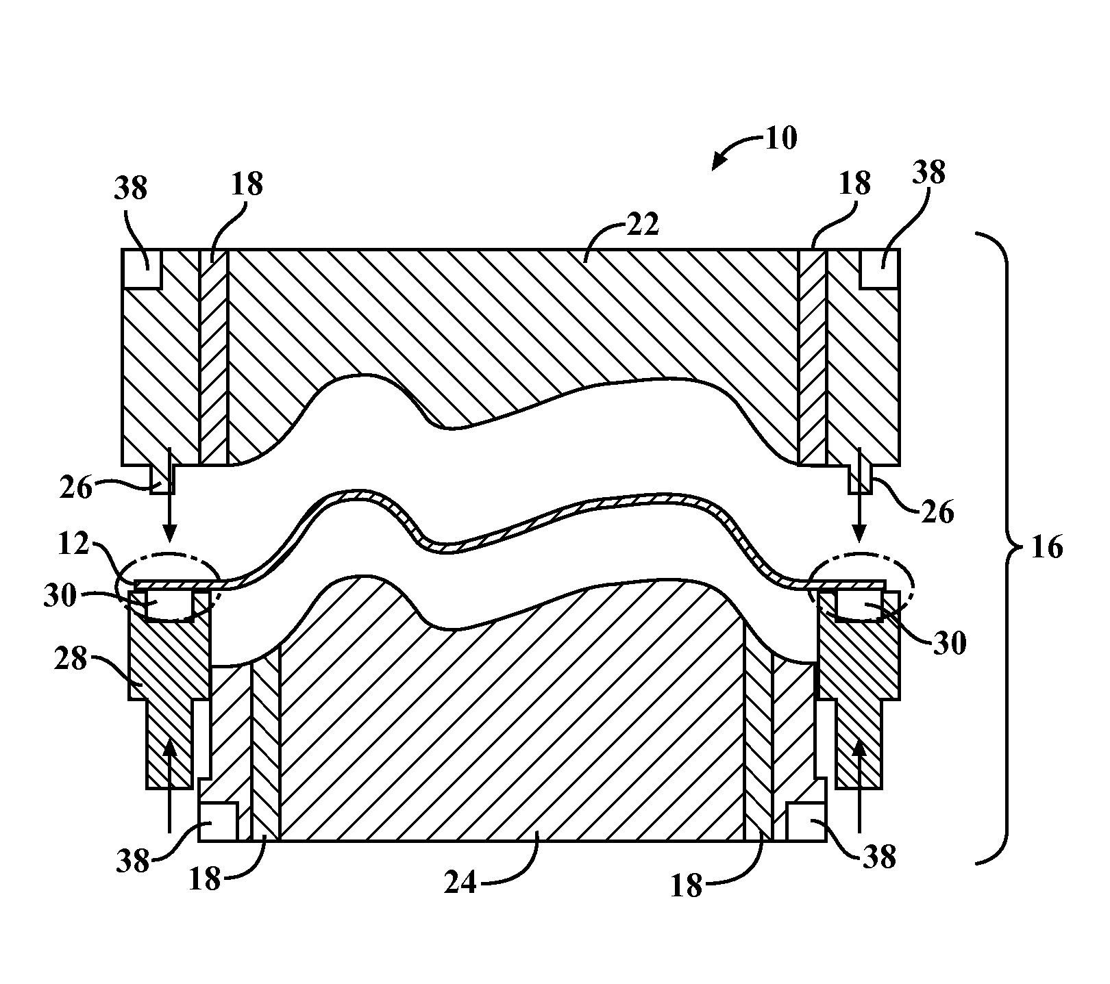
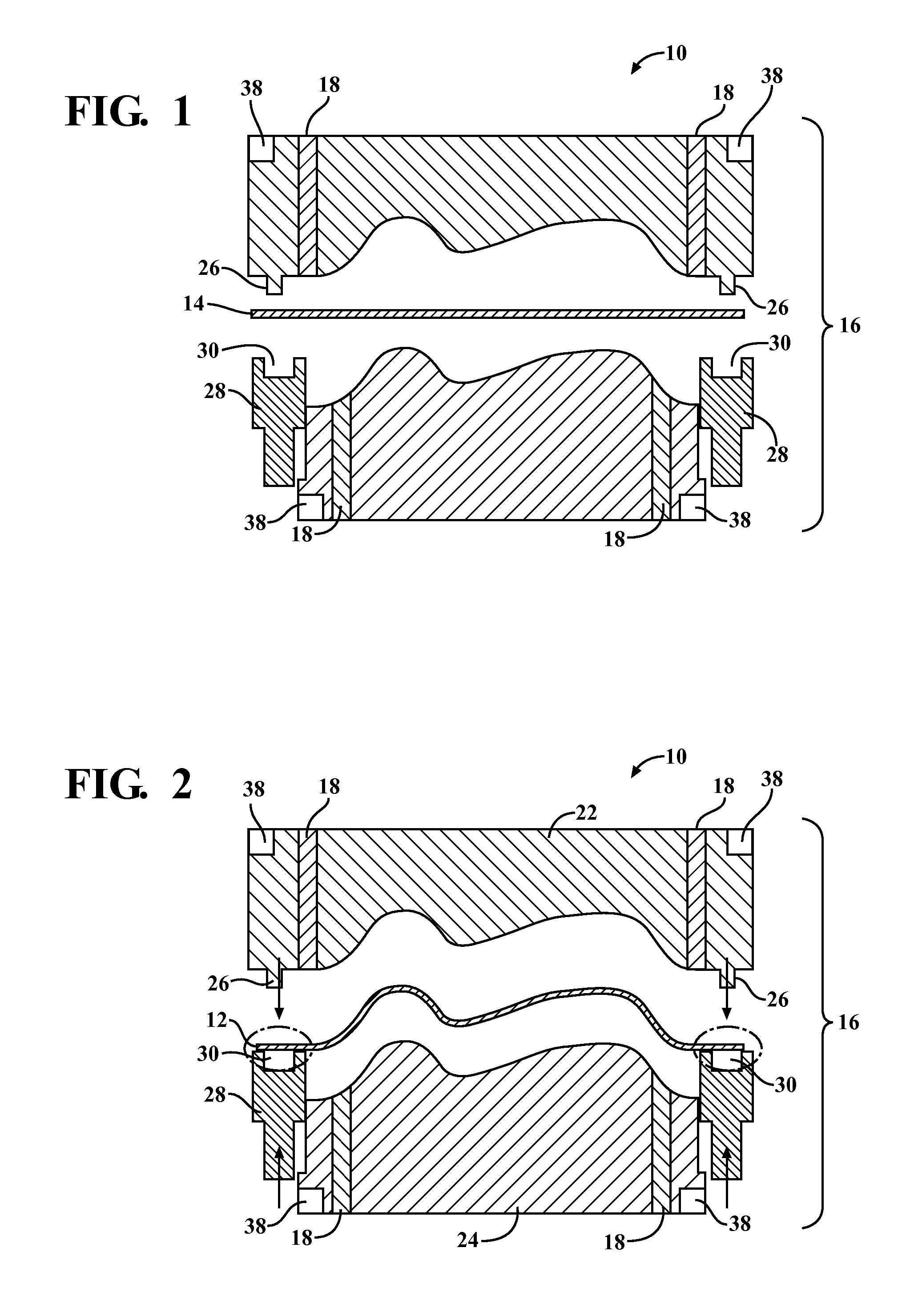
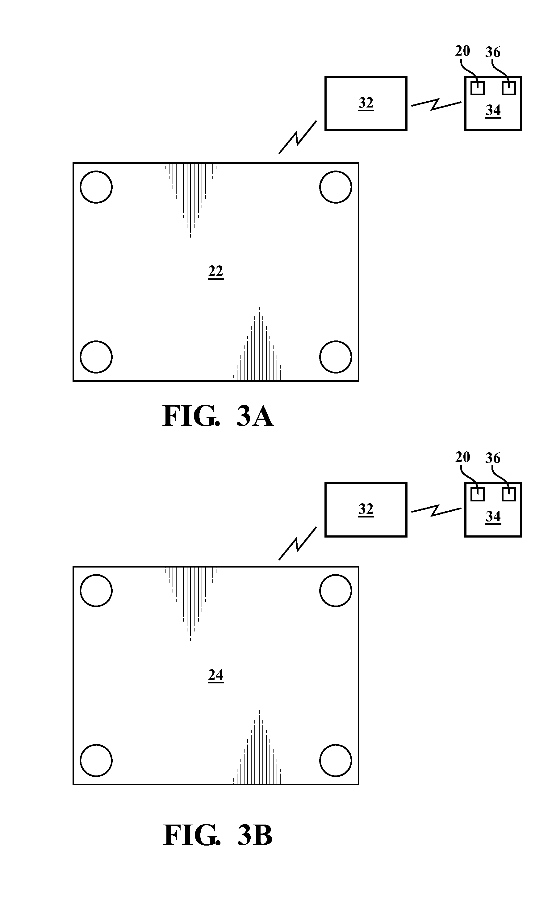
[0023]Referring to FIGS. 1-8, a system 10 for controlling the quality of a part 12 stamped from a blank of material 14 is provided. The system 10 includes at least one die 16 operable to stamp the blank of material 14 into a desired part 12. A sensor 18 monitors the forces exerted by the die 16. The forces are compared to a profile 20. The profile 20 includes the forces generated during a stamping operation of a properly formed part 12. The profile 20 shows the proper distribution of forces with respect to time. The system 10 labels a part 12 defective when the forces measured differ a predetermined amount from the profile 20.

[0024]With reference first to FIGS. 1 and 2, an operation of the die 16 is provided. The die 16 has an upper die 22 and a lower die 24, referenced herein as a slide press 22 and a die cushion 24 respectively. The slide press 22 includes tabs 26. The tabs 26 are shown on opposing sides of the slide press 22. The die 16 further includes a pair of binders 28 each ...


PUM

PropertyMeasurementUnit
forcesaaaaaaaaaa
forceaaaaaaaaaa
slide forceaaaaaaaaaa

Abstract

A system and method for detecting a defective part and the type of defect formed during stamping operations. The system and method will not only detect the defect but also the nature of the defect and the time at which the defect occurred during stamping operations. Such information is useful not only in quality control but also in isolating a problem which may exist in stamping operations and thus eliminating time for isolating such problems and correcting them. The system and method uses a profile of a properly stamped part to detect a defect, and the root cause of the defect.

Description

CROSS-REFERENCE TO RELATED APPLICATIONS[0001]This application is a divisional of U.S. patent application Ser. No. 13 / 041,857 filed on Mar. 7, 2011, which is incorporated in its entirety herein by reference.FIELD OF THE INVENTION[0002]The invention relates to a system for stamping a part from a blank of material. More particularly, the invention relates to a system and method for detecting abnormalities in the part stamped by a die using forces measured during stamping operations and comparing them with a profile of forces for a properly stamped part.BACKGROUND OF THE INVENTION[0003]Stamping operations are done using a die. The die includes an upper die and a lower die, also referenced herein as a slide press and a die cushion respectively. A sheet of material, also referenced in the art as a blank, is placed between the slide and die cushion and the slide and die cushion are pressed against each other so as to form the blank into a desired part.[0004]The part may then be visually in...

Claims


Application Information

Patent Timeline
Patent Type & Authority Applications(United States)
IPC IPC(8): B21C51/00B21D22/02
CPCB21D22/02B21C51/005B21C51/00B21J9/20
Inventor WALTER, JOSHUA A.H.GRAVIS, MICHAEL J.APPS, CHARLES DAVID
Owner TOYOTA MOTOR ENGINEERING & MANUFACTURING NORTH AMERICA
Why Eureka
Try Eureka