Solar cell and method of fabricating the same

a solar cell and precursor technology, applied in the field of solar cells, can solve the problems of increasing the shunt path, affecting the production efficiency of final products, and the difficulty of fabricating aluminum precursors for mocvds, so as to reduce the influence of buffer layer, prevent electric shorts, and reduce plasma damage to the substrate

Active Publication Date: 2015-04-23
LG INNOTEK CO LTD
View PDF4 Cites 1 Cited by
  • Summary
  • Abstract
  • Description
  • Claims
  • Application Information

AI Technical Summary

Benefits of technology

[0014]In the solar cell and the method of fabricating the same according to the embodiment, the front electrode layer can be formed without performing a sputtering process, so that an influence on the buffer layer can be reduced. That is, plasma damage to the substrate is reduced so that electric short can be prevented and a fill factor can be increased. Accordingly, performance of a solar cell apparatus can be improved.

Problems solved by technology

The sputtering process causes a problem in that plasma damage is applied to the buffer layer so that a shunt path is increased.
However, the method using the MOCVD has a difficulty in fabricating a precursor of aluminum for the MOCVD.
In the method using the non-vacuum deposition, aluminum is not uniformly distributed during sintering and properties of the front electrode layer may be deteriorated due to a local cohesion property.

Method used


Image

  • Solar cell and method of fabricating the same
  • Solar cell and method of fabricating the same
  • Solar cell and method of fabricating the same

Examples


Embodiment Construction

[0018]In the description of the embodiments, it will be understood that, when a substrate, a layer, a film, or an electrode is referred to as being “on” or “under” another substrate, another layer, another film, or another electrode, it can be “directly” or “indirectly” on the other substrate, layer, film, or electrode, or one or more intervening layers may also be present. Such a position of the layer has been described with reference to the drawings.

[0019]The size or the thickness of the layer (film), the region, the pattern or the structure may be modified exaggerated for the purpose of explanation and clarity. The size may not utterly reflect the actual size.

[0020]Hereinafter, an exemplary embodiment of the disclosure will be described with reference to the accompanying drawings.

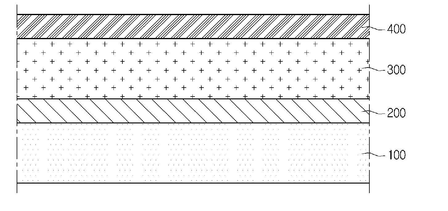
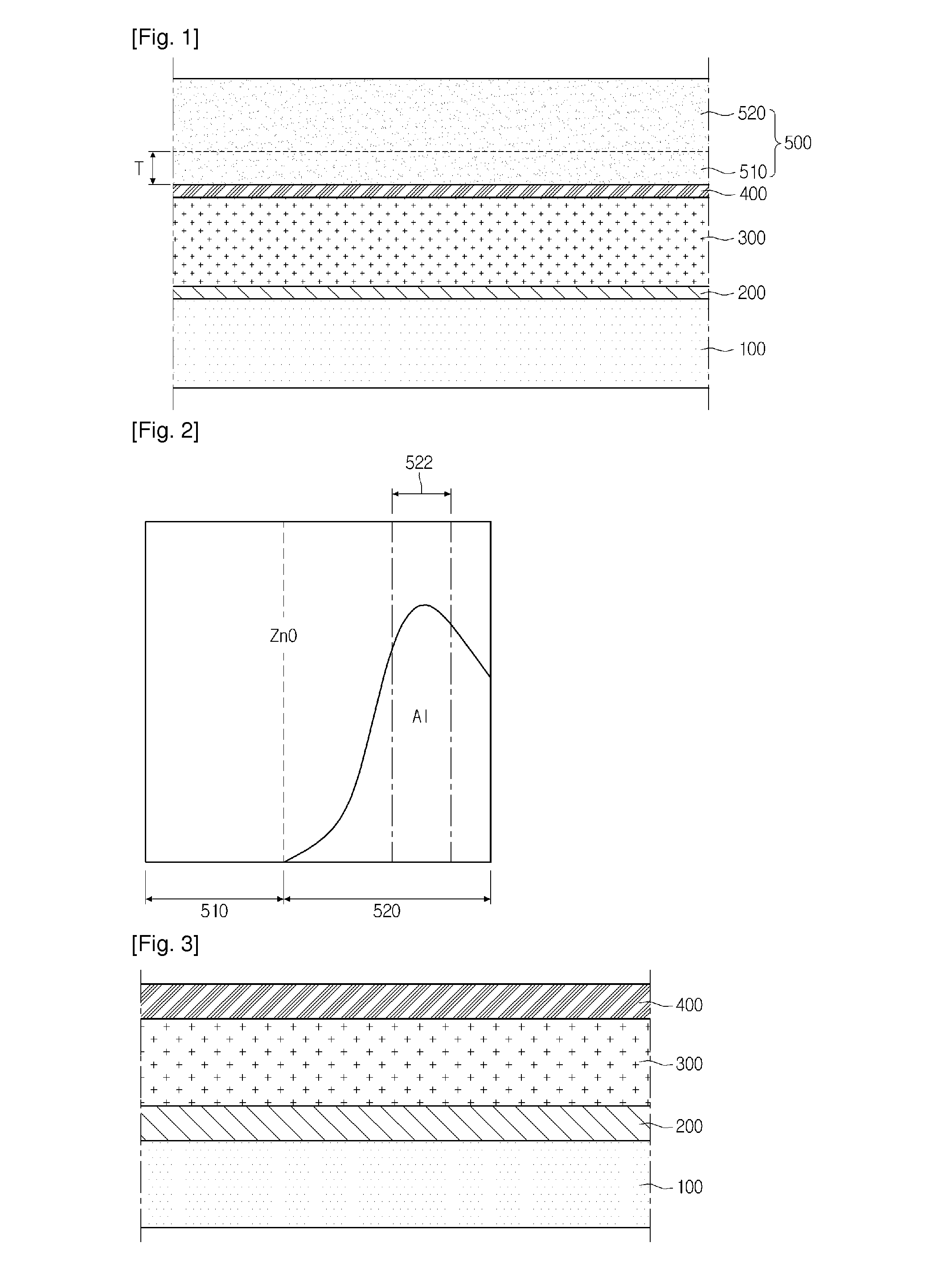
[0021]The solar cell according to the embodiment will now be described in detail with reference to FIGS. 1 and 2. FIG. 1 is a sectional view showing one section of a solar cell according to the embodimen...


PUM


Abstract

According to the embodiment, there is provided a solar cell including: a back electrode layer; a light absorbing layer on the back electrode layer; a buffer layer on the light absorbing layer; and a front electrode layer on the buffer layer, wherein the front electrode layer comprises an intrinsic region and a doping region having a conductive dopant, and a concentration of the conductive dopant is gradually lowered in upward and downward directions from an excess doping region of the doping region.

Description

TECHNICAL FIELD[0001]The embodiment relates to a solar cell and a method of fabricating the same.BACKGROUND ART[0002]A method of fabricating a solar cell for solar light power generation is as follows. First, after preparing a substrate, a back electrode layer is formed on the substrate and patterned by a laser, thereby forming a plurality of back electrodes.[0003]Thereafter, a light absorbing layer, a buffer layer, and a high resistance buffer layer are sequentially formed on the back electrodes. Various schemes, such as a scheme of forming a Cu(In,Ga)Se2 (CIGS) based-light absorbing layer by simultaneously or separately evaporating Cu, In, Ga, and Se and a scheme of performing a selenization process after a metallic precursor film has been formed, have been extensively used in order to form the light absorbing layer. The energy band gap of the light absorbing layer is in the range of about 1 eV to 1.8 eV.[0004]Then, a buffer layer including cadmium sulfide (CdS) is formed on the l...

Claims


Application Information

Patent Timeline
Patent Type & Authority Applications(United States)
IPC IPC(8): H01L31/0224H01L31/18
CPCH01L31/1884H01L31/022466H01L31/03923H01L31/0749Y02E10/541Y02P70/50H01L31/04H01L31/18
Inventor LIM, CHIN WOO
Owner LG INNOTEK CO LTD
Why Eureka
Try Eureka