Braking device for vehicle

a technology for brake devices and vehicles, applied in brake action initiation, brake systems, vehicle components, etc., can solve the problems of brake operation feeling discomfort for drivers, waste of hydraulic pressure in power hydraulic pressure sources, and leakage of working fluid

Inactive Publication Date: 2015-04-23
TOYOTA JIDOSHA KK
View PDF7 Cites 8 Cited by
  • Summary
  • Abstract
  • Description
  • Claims
  • Application Information

AI Technical Summary

Benefits of technology

[0022]As a result, under a state in which the hydraulic pressure is supplied from the pressure increasing mechanism, the hydraulic pressure increased by the pressure increasing mechanism may be preferentially transmitted to the wheel cyl

Problems solved by technology

Moreover, in the related-art hydraulic brake control device and brake system, for example, if a leak of the working fluid or the like occurs in a flow passage between the pressure increasing mechanism and the wheel cylinder, namely, in a brake syste

Method used


Image

  • Braking device for vehicle
  • Braking device for vehicle
  • Braking device for vehicle

Examples


first embodiment

a-1. Modified Example of First Embodiment

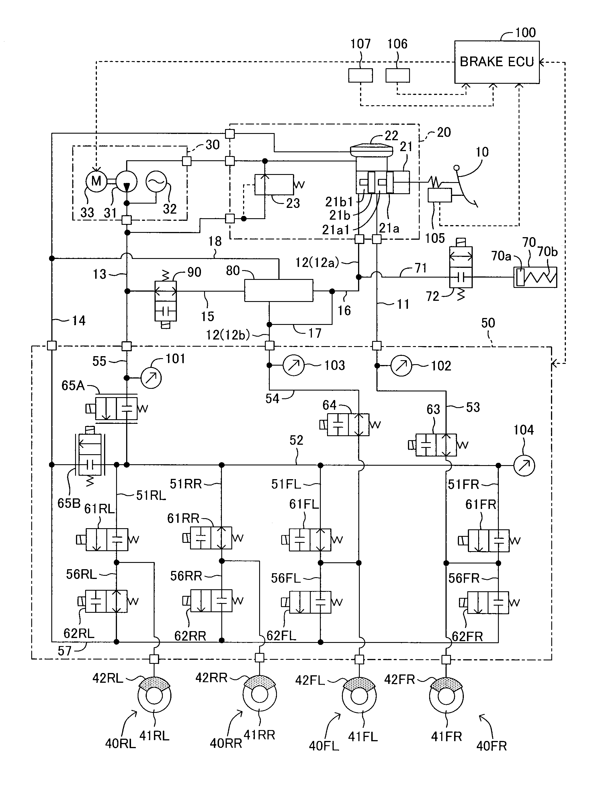
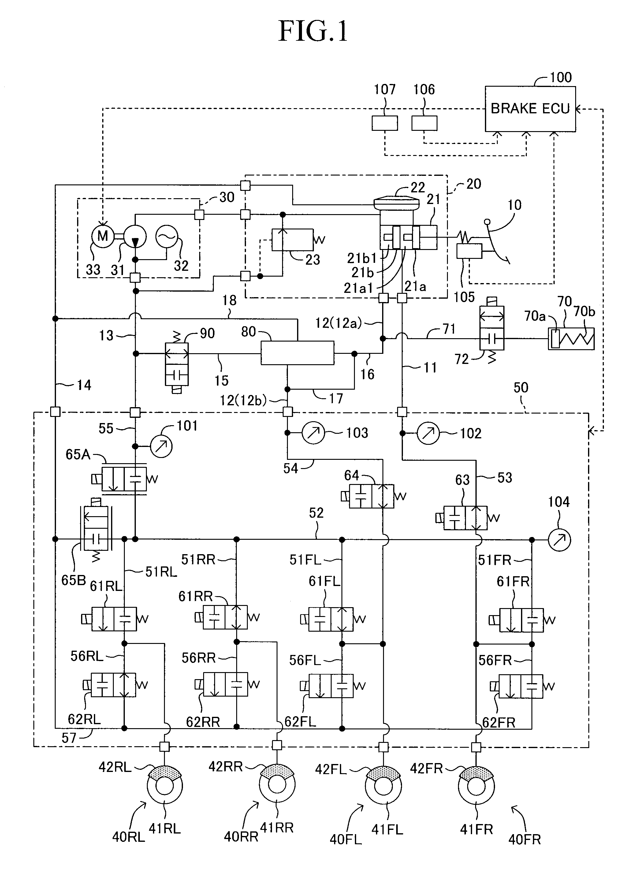
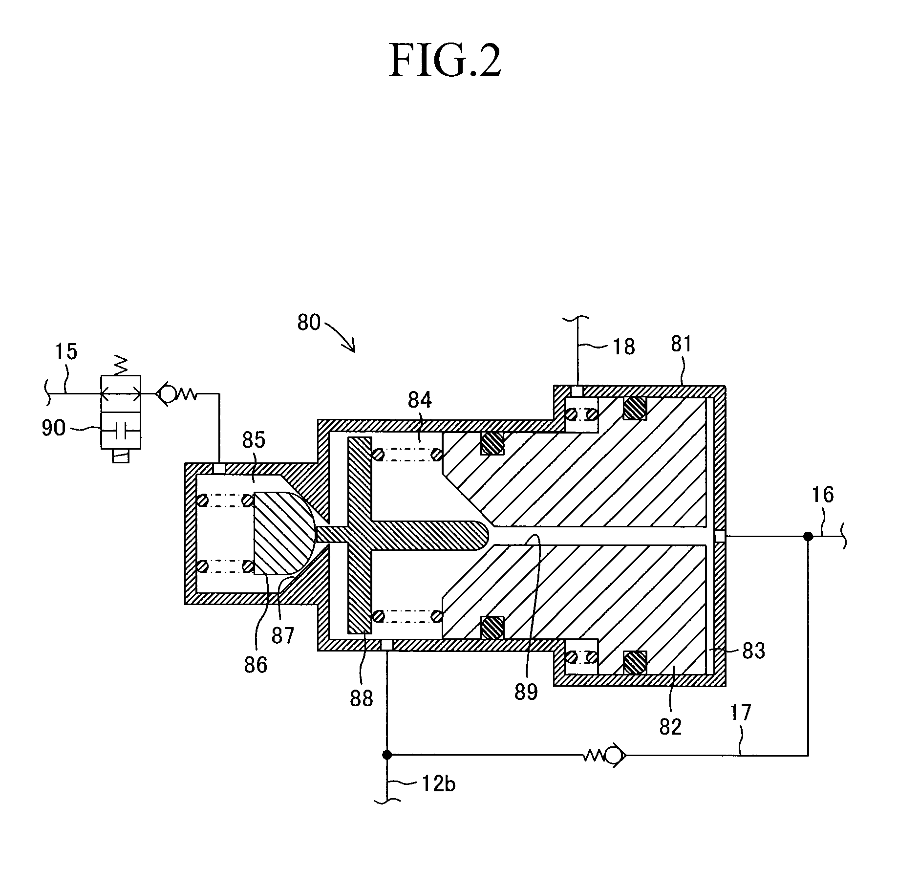
[0092]In the first embodiment, the current is always supplied to the solenoid of the normally-open pressure increasing mechanism cut valve 90 so as to be maintained in the closed state in the linear control mode, in other words, during the normal control of the vehicle brake device. As a result, for example, when a sealing performance abnormality occurs in the high pressure supply valve 86 and the valve seat 87 of the pressure increasing mechanism 80, the working fluid (accumulator pressure Pacc) in the high pressure chamber 85 is surely prevented from flowing backward via the small diameter chamber 84, the communication passage 89, and the large diameter chamber 83 to the master cylinder 21, and when a sealing performance abnormality occurs in the stepped piston 82 and the valve opening member 88, the working fluid at the high pressure (servo pressure) in the small diameter chamber 84 is surely prevented from flowing backward via the communi...

second embodiment

b-1. Modified Example of Second Embodiment

[0114]The filters 19a, 19b, and 19c are respectively provided on the high pressure supply passage 15, the pilot passage 16, and the master pressure pipe 12b according to the second embodiment. In this case, the pressure increasing mechanism 80 has such a structure that the pilot passage 16 and the master pressure pipe 12b communicate via the communication passage 89 to each other, and such a modified example that the filter 19b is provided only on the pilot passage 16, in other words, such a modified example that the filter 19a provided on the high pressure supply passage 15 and the filter 19c provided on the master pressure pipe 12b are omitted may be provided. In the modified example of the second embodiment, the filter 19b is provided only on the pilot passage 16, but, as described above, the filter 19b can remove the foreign matters affecting the sealing performance between the high pressure supply valve 86 and the valve seat 87 of the p...


PUM


Abstract

A master cylinder generates a master cylinder pressure in response to a stepping operation by a driver on a brake pedal. A power hydraulic pressure generation device includes a pressurizing pump and an accumulator, and a hydraulic pressure of a working fluid pressurized by the pressurizing pump is accumulated by the accumulator as an accumulator pressure. A pressure increasing mechanism communicates to the master cylinder and the accumulator, mechanically moves in response to the master cylinder pressure supplied from the master cylinder, and uses the accumulator pressure supplied from the accumulator to generate a servo pressure. A pressure increasing mechanism cut valve serving as a shut-off valve is a normally-closed electromagnetic on-off valve, and is provided on a high pressure supply passage for communication between the accumulator and the pressure increasing mechanism. The pressure increasing mechanism cut valve is controlled by a brake ECU to be in a closed state for shutting off the communication between the accumulator and the pressure increasing mechanism.

Description

TECHNICAL FIELD[0001]The present invention relates to a vehicle brake device configured to selectively use a power hydraulic pressure source and a master cylinder as a hydraulic pressure source, and more particularly, to a vehicle brake device including a pressure increasing mechanism connected to a power hydraulic pressure source and a master cylinder.BACKGROUND ART[0002]In recent years, there has been proposed a brake device including a pressurizing pump (accumulator) serving as a power hydraulic pressure source, and a pressure increasing mechanism configured to use a hydraulic pressure of the pressurizing pump (accumulator) to increase the hydraulic pressure from a master cylinder and output the increased hydraulic pressure. The brake device is configured to selectively use the hydraulic pressure from the pressurizing pump (accumulator) and the hydraulic pressure from the pressure increasing mechanism. For example, as a brake device of this type, hitherto, a hydraulic brake contr...

Claims


Application Information

Patent Timeline
IPC IPC(8): B60T13/14B60T13/68
CPCB60T13/148B60T13/142B60T13/686B60T8/4081B60T8/885B60T13/146B60T7/042B60T13/662
Inventor MIYAZAKI, TETSUYA
Owner TOYOTA JIDOSHA KK
Why Eureka
Try Eureka