Transfer method and thermal nanoimprinting apparatus

Inactive Publication Date: 2015-04-23
ASAHI KASEI E-MATERIALS CORPORATION
View PDF6 Cites 19 Cited by
  • Summary
  • Abstract
  • Description
  • Claims
  • Application Information

AI Technical Summary

Benefits of technology

[0021]Through the present invention, a transfer method and a thermal nanoimprinting apparatus can be provided whereby a concavo-convex structure can be tra

Problems solved by technology

However, in a photolithography technique, it is difficult to fabricate a concavo-convex structure having a size smaller than the wavelength of light used for light exposure.
An EB method has drawbacks in that the mask concavo-convex structure is drawn directly by an electron beam, and the drawing time therefore increases with the number of drawn the concavo-convex structure, and throughput of forming the concavo-convex structure is markedly reduced.
Due to high accuracy control of the mask position in an exposure apparatus for photolithography, increased size of the electron-beam lithography apparatus in an exposure apparatus for an EB method, and other factors, the abovementioned methods have the drawback of high equipment cost.
It is therefore difficult to prevent entrapment of bubbles or to equalize the pressure distribution during pressing.
Entrapment of bubbles reduces the transfer accuracy of the concavo-convex structure, and a large pressure distribution leads to significant unevenness of the film thickness of the liquid resist layer.
In particular, the larger the area of the concavo-convex structure used for transfer becomes, the more difficult it becomes to achieve a uniform pressure and increase the area.
The stress applied to the concavo-convex structure of the resist layer on w

Method used


Image

  • Transfer method and thermal nanoimprinting apparatus
  • Transfer method and thermal nanoimprinting apparatus
  • Transfer method and thermal nanoimprinting apparatus

Examples


Example

First Embodiment

[0196]FIG. 14 is a schematic view showing the thermal nanoimprinting apparatus pertaining to a first embodiment. The thermal nanoimprinting apparatus 200 is provided with a feeding roller 202 on which a long fine-pattern-forming film 101 is wound. The feeding roller 202 sends out the fine-pattern-forming film 101 at a predetermined speed. A take-up roller 203 paired with the feeding roller 202 is provided for winding the sent fine-pattern-forming film 101. The rotation speed of the take-up roller 203 and the rotation speed of the feeding roller 202 may be controlled so that the delivery speed and the take-up speed of the fine-pattern-forming film 101 are synchronized, but a dancer roller, a torque motor, a tension controller, or the like can be used to control the tension of the fine-pattern-forming film 101. The mechanism for conveying the fine-pattern-forming film 101 may therefore be designed, as appropriate, in accordance with the tension control scheme employed....

Example

Second Embodiment

[0242]FIG. 18 is a schematic view showing the thermal nanoimprinting apparatus pertaining to a second embodiment. In the description below, constituent members that are the same as those described in the first embodiment are referred to by the same reference numerals, and no description thereof will be given.

[0243]The thermal nanoimprinting apparatus 300 pertaining to the second embodiment differs from the first embodiment in that a cutting part 501 is provided.

[0244](Cutting Part)

[0245]As shown in FIG. 18, a cutting part 501 is provided downstream from the laminating part 201 and previous to the take-up roller 203 in the conveying direction MD. A gap sufficient for jointly providing an energy-ray irradiation part or other optional constituent element is preferably provided between the rotating body 102 and the cutting part 501, or between the take-up roller 203 and the cutting part 501.

[0246]The cutting part 501 completely or partially cuts the fine-pattern-forming...

Example

Third Embodiment

[0263]The thermal nanoimprinting apparatus pertaining to a third embodiment will next be described in detail with reference to the drawings. The thermal nanoimprinting apparatus pertaining to the third embodiment has a peeling part 206, the same as in the thermal nanoimprinting apparatus 200 pertaining to the first embodiment. Constituent members that are the same as those described in the embodiments above are referred to by the same reference numerals, and no description thereof will be given.

[0264]FIG. 20 is a schematic view showing the thermal nanoimprinting apparatus pertaining to the third embodiment. The thermal nanoimprinting apparatus 600 pertaining to the third embodiment is provided with a feeding roller 202 on which a long fine-pattern-forming film 101 is wound. The feeding roller 202 sends out the fine-pattern-forming film 101 at a predetermined speed. A take-up roller 203 paired with the feeding roller 202 is provided for winding the sent fine-pattern-f...


PUM

PropertyMeasurementUnit
Temperatureaaaaaaaaaa
Forceaaaaaaaaaa
Widthaaaaaaaaaa

Abstract

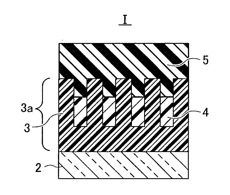
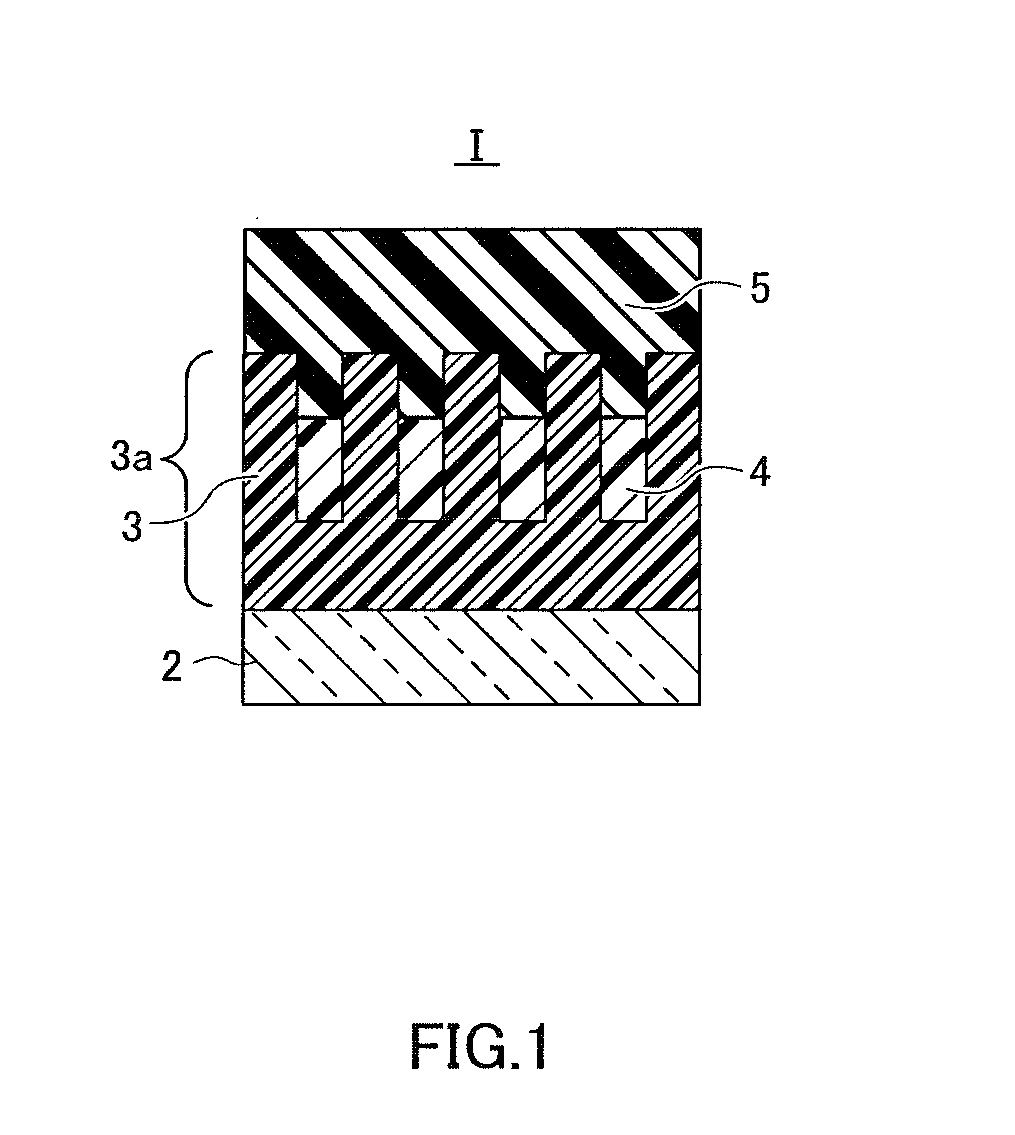
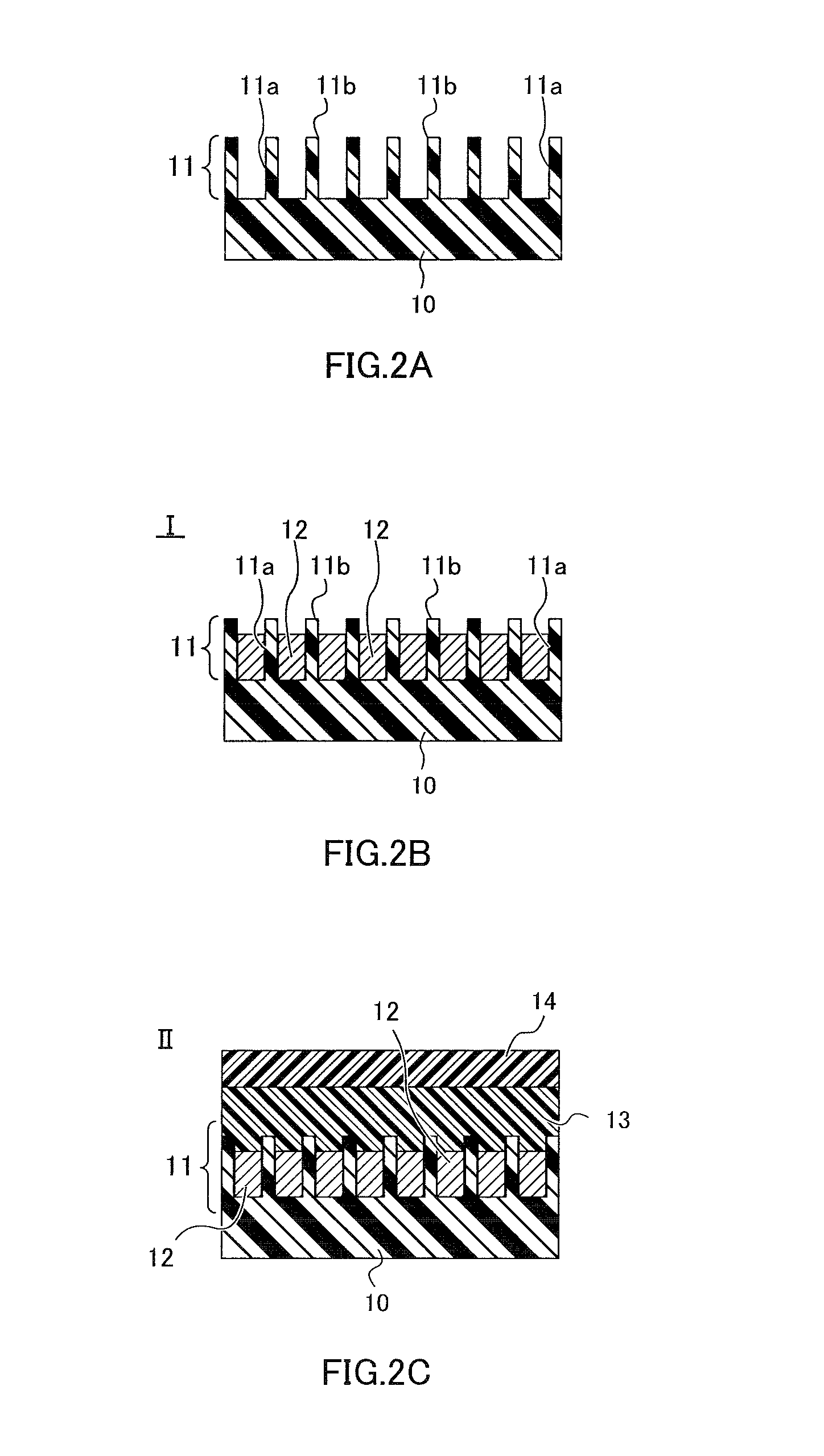
A first mask layer (13) and a second mask layer (12) are transferred and imparted to a target object (20) using a fine-pattern-forming film (I) provided with a cover film (10) having a nanoscale concavo-convex structure (11) formed on one surface thereof, a second mask layer (12) provided in a recess of the concavo-convex structure (11), and a first mask layer (13) provided so as to cover the concavo-convex structure (11) and the second mask layer (12). A surface of a fine-pattern-forming film (II) to which the first mask layer (13) is provided is pressed toward a surface of the target object (20), energy rays are irradiated to the first mask layer (13), and the cover film (10) is then separated from the second mask layer (12) and the first mask layer (13). Pressing and energy ray irradiation are each performed independently. The target object is etched using the second mask layer (12) and the first mask layer (13).

Description

TECHNICAL FIELD[0001]The present invention relates to a transfer method and to a thermal nanoimprinting apparatus.TECHNICAL BACKGROUND[0002]Photolithography techniques have recently come to be frequently used as techniques for fabricating a concavo-convex structure in LSI manufacturing. However, in a photolithography technique, it is difficult to fabricate a concavo-convex structure having a size smaller than the wavelength of light used for light exposure. Other techniques for fabricating the concavo-convex structure include mask concavo-convex structure lithography using an electron-beam lithography apparatus (EB method). An EB method has drawbacks in that the mask concavo-convex structure is drawn directly by an electron beam, and the drawing time therefore increases with the number of drawn the concavo-convex structure, and throughput of forming the concavo-convex structure is markedly reduced. Due to high accuracy control of the mask position in an exposure apparatus for photol...

Claims


Application Information

Patent Timeline
IPC IPC(8): B29C59/02B29C59/04B29C59/16
CPCB29C59/022B29C59/16B29K2105/0005B29C59/046B29K2033/08B29C59/026G03F7/0002Y10T428/24628B29C59/04H01L21/0274
Inventor HOSOMI, NAOKIKOIKE, JUNYAMAGUCHI, FUJITO
Owner ASAHI KASEI E-MATERIALS CORPORATION
Why Eureka
Try Eureka