Multiple tap aspirator

a vacuum-powered aspirator and tap-type technology, applied in the direction of liquid fuel feeders, machines/engines, combustion-air/fuel-air treatment, etc., can solve the problems of vacuum reservoir vacuum loss, inability to use, etc., and achieve the effect of low-cost vacuum generation

Active Publication Date: 2015-04-30
FORD GLOBAL TECH LLC
View PDF3 Cites 33 Cited by
  • Summary
  • Abstract
  • Description
  • Claims
  • Application Information

AI Technical Summary

Benefits of technology

[0002]Vehicle engine systems may include various vacuum consumption devices that are actuated using vacuum. These may include, for example, a brake booster. Vacuum used by these devices may be provided by a dedicated vacuum pump, such as an electrically-driven or engine-driven vacuum pump. As an alternative to such resource-consuming vacuum pumps, one or more aspirators may be coupled in an engine system to harness engine airflow for generation of vacuum. Aspirators (which may alternatively be referred to as ejectors, venturi pumps, jet pumps, and eductors) are passive devices which provide low-cost vacuum generation when utilized in engine systems. An amount of vacuum generated at an aspirator can be controlled by controlling the motive air flow rate through the aspirator. For example, when incorporated in an engine intake system, aspirators may generate vacuum using energy that would otherwise be lost to throttling, and the generated vacuum may be used in vacuum-powered devices such as brake boosters.
[0004]To address at least some of these issues, the inventors herein have identified a multiple tap aspirator which, when incorporated in an engine system, provides both high vacuum generation and high suction flow, and may be operated with a low pressure difference driving motive flow, during intermittent motive flow conditions. In one example, an engine system includes an aspirator with a suction tap in a throat of the aspirator, a suction tap in a diverging cone of the aspirator, and a suction tap in a straight tube downstream of the diverging cone. The inventors have recognized that placement of suction taps in the throat, diverging cone, and straight exit tube of the aspirator advantageously maximizes vacuum generation while enabling a high suction flow rate, in that this placement combines the advantages of throat tap aspirators (e.g., high vacuum generation) with the advantages of aspirators with taps arranged downstream of the throat (e.g., high suction flow). Inclusion of a tap in the exit tube (e.g., a straight, unconstricted tube downstream of the aspirator's diverging cone) advantageously enables fast pull-down of a vacuum source, such as a brake booster. Further, the inventors have recognized that such an aspirator may be powered by vacuum rather than compressed air. For example, a motive inlet of the aspirator may be coupled with atmosphere, and a mixed flow outlet of the aspirator coupled with a vacuum source, such that the pressure differential between atmosphere and the vacuum source induces flow through the aspirator. In other examples, the multiple tap aspirator may be coupled between an engine crankcase and a low pressure sink of the engine intake system such as the compressor inlet or intake manifold, so as to generate vacuum via crankcase ventilation flow. Furthermore, by including only a single check valve in the path between the source of suction flow and each suction tap of the aspirator, flow losses which often occur in staged aspirators featuring multiple check valves in the suction flow path may be reduced.

Problems solved by technology

Staged aspirators including multiple suction ports or taps may be used, but such aspirators tend to suffer from various disadvantages.
For example, staged aspirators may rely on a motive flow of compressed air, and may not be usable in configurations where motive flow is intermittent (e.g., intermittent motive flow may result in vacuum reservoir vacuum loss in some examples).
Further, staged aspirators may be configured such that suction flow must pass through multiple check valves en route to the suction port(s) of the aspirator, which may disadvantageously result in flow losses.

Method used


Image

  • Multiple tap aspirator
  • Multiple tap aspirator
  • Multiple tap aspirator

Examples


second embodiment

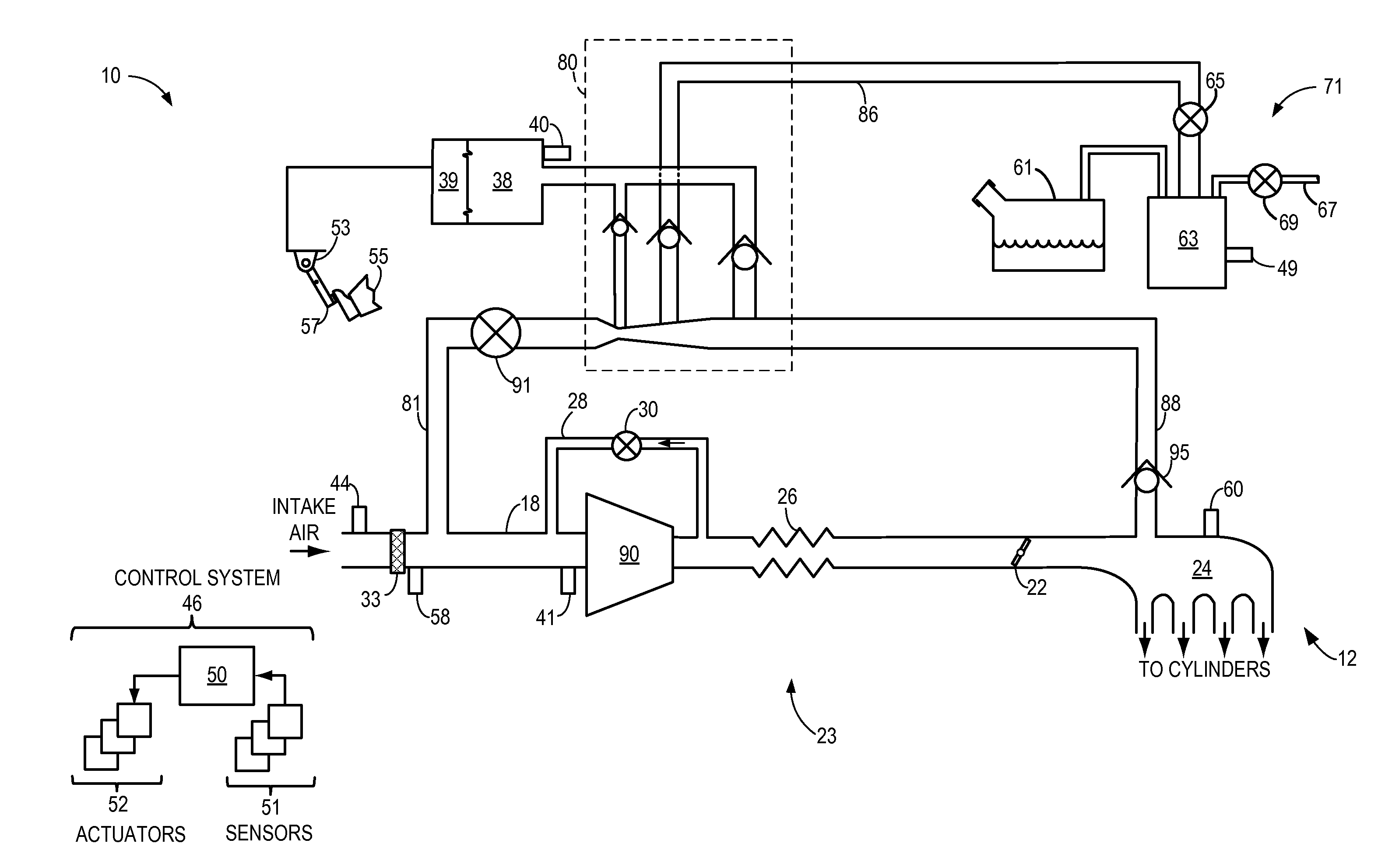
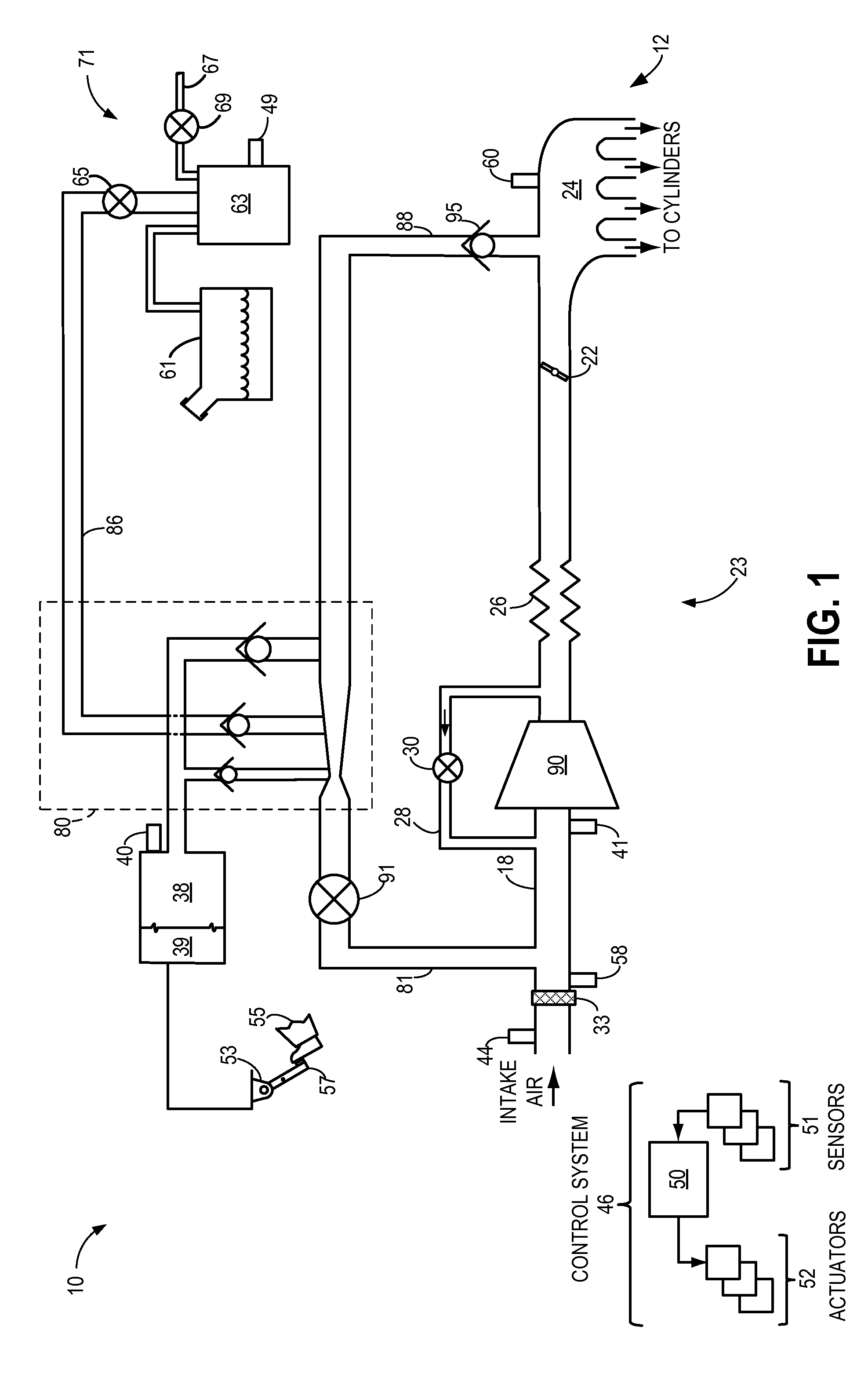
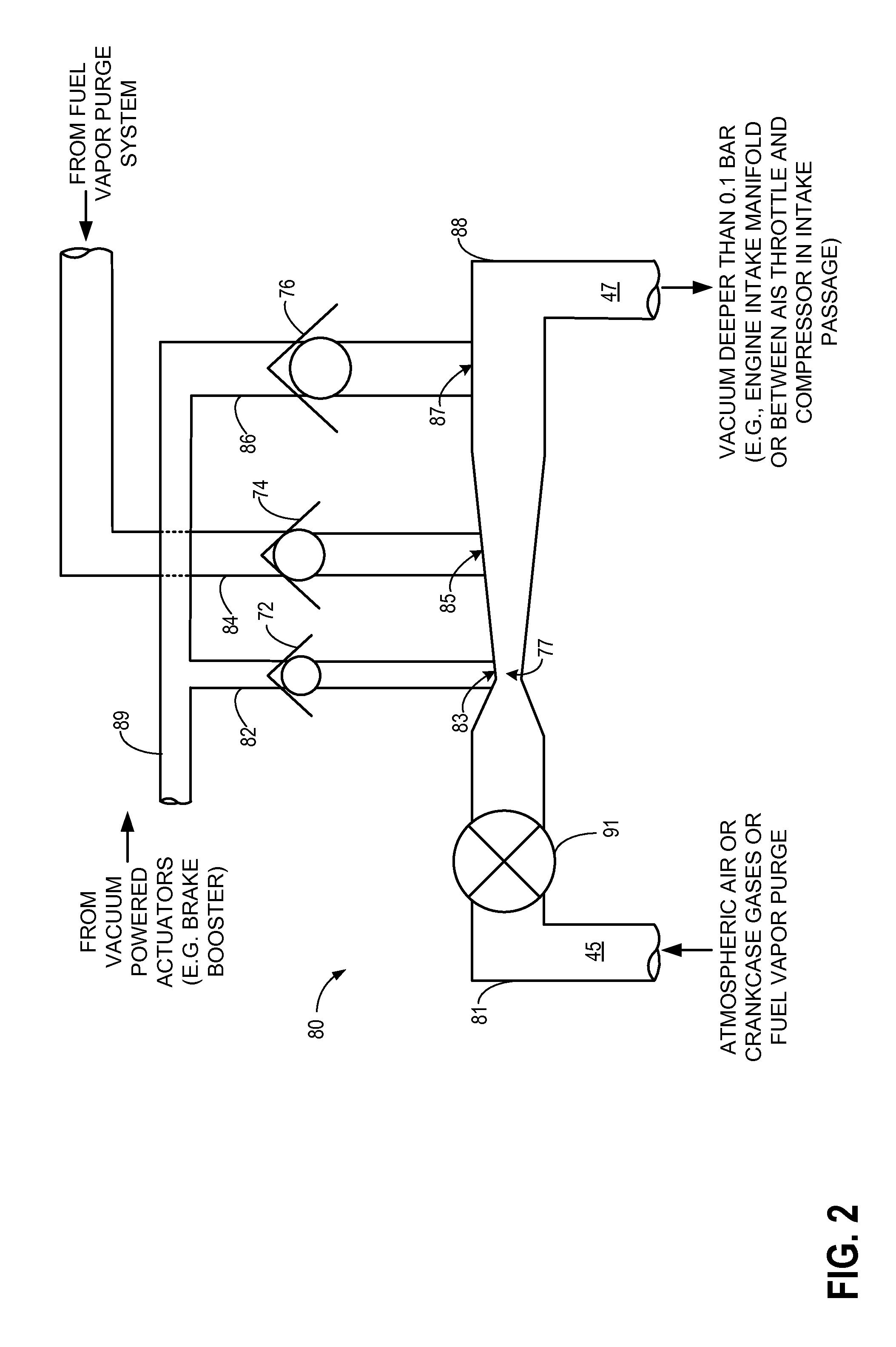
[0044]Further, in contrast to the embodiment of FIGS. 1-2 wherein a CIP sensor is arranged immediately upstream of the compressor, in the second embodiment a sensor 341 is arranged in intake passage 318 in the vicinity of a juncture of passage 388 and intake passage 318 (e.g., downstream of AIS throttle 331 and upstream of a juncture of bypass passage 328 and intake passage 318). Sensor 341 may provide a signal to controller 50 regarding the pressure at the motive outlet of aspirator 380.

[0045]Another difference between the first embodiment and the second embodiment involves the suction flow sources for aspirator 380. In the first embodiment, the suction passages for the throat tap and exit tube tap merge into a common passage which is coupled with vacuum reservoir 38 for use by vacuum actuators 39, whereas the suction passage for the diverging cone tap is coupled with a fuel vapor purge system 71. In contrast, in the second embodiment, all three suction passages merge into a common...

first embodiment

[0068]After 806, method 800 proceeds to 808. At 808, method 800 includes measuring and / or estimating the composition and amount of fluid exiting the mixed flow outlet of the aspirator. For example, the composition and amount of fluid exiting the mixed flow outlet of the aspirator may be estimated based on the flow levels in each suction tube of the aspirator determined at step 806 and further based on parameter values detected by various sensors. In the context of the first embodiment, where suction flow entering the exit tube tap includes some concentration of fuel vapors from the fuel vapor canister, the composition of the fluid exiting the mixed flow outlet of the aspirator may be based on the relative amounts of suction flow in the three suction taps (as determined at 806, for example) and based on an inference of fuel vapor concentration exiting the fuel vapor canister. The inference may be based on sensed exhaust gas composition, for example. Alternatively, dedicated sensors m...


PUM


Abstract

Systems and methods are provided for engine systems including a vacuum-powered multiple tap aspirator coupled between atmospheric, an engine crankcase, or another source and a vacuum source such as a compressor inlet or engine intake manifold. The multiple tap aspirator includes a suction tap arranged in a throat of the aspirator, a suction tap arranged in a diverging cone of the aspirator, and a suction tap arranged in a straight exit tube downstream of the diverging cone of the aspirator. The aspirator provides vacuum generation and suction flow over a range of vacuum levels at the suction taps, and suction flow only passes through a single check valve before entering the aspirator.

Description

FIELD[0001]The present invention relates to a vacuum-powered aspirator with multiple taps which may be included in an engine system.BACKGROUND AND SUMMARY[0002]Vehicle engine systems may include various vacuum consumption devices that are actuated using vacuum. These may include, for example, a brake booster. Vacuum used by these devices may be provided by a dedicated vacuum pump, such as an electrically-driven or engine-driven vacuum pump. As an alternative to such resource-consuming vacuum pumps, one or more aspirators may be coupled in an engine system to harness engine airflow for generation of vacuum. Aspirators (which may alternatively be referred to as ejectors, venturi pumps, jet pumps, and eductors) are passive devices which provide low-cost vacuum generation when utilized in engine systems. An amount of vacuum generated at an aspirator can be controlled by controlling the motive air flow rate through the aspirator. For example, when incorporated in an engine intake system,...

Claims


Application Information

Patent Timeline
Patent Type & Authority Applications(United States)
IPC IPC(8): F02M35/10F04F5/52F04F5/14
CPCF02M35/10229F04F5/52F04F5/14B60K25/04B60T17/02F02M35/10222F02M35/10275F02M35/1272F02M35/1294F02M25/089F02M35/10118F01M13/02F01M13/04F02M25/08F02M35/10
Inventor PURSIFULL, ROSS DYKSTRAVANDERWEGE, BRAD ALAN
Owner FORD GLOBAL TECH LLC
Why Eureka
Try Eureka