
Injection nozzle

a technology of injection nozzles and nozzles, which is applied in the direction of wear-reducing fuel injection, machine/engine, engine components, etc., can solve the problems of weak wear poor lubrication properties of alternative fuels and low-sulphur fuels, and poor wear resistance of the components of the fuel injection system

Inactive Publication Date: 2015-04-30
CATERPILLAR MOTOREN
View PDF10 Cites 1 Cited by
  • Summary
  • Abstract
  • Description
  • Claims
  • Application Information

AI Technical Summary

Benefits of technology

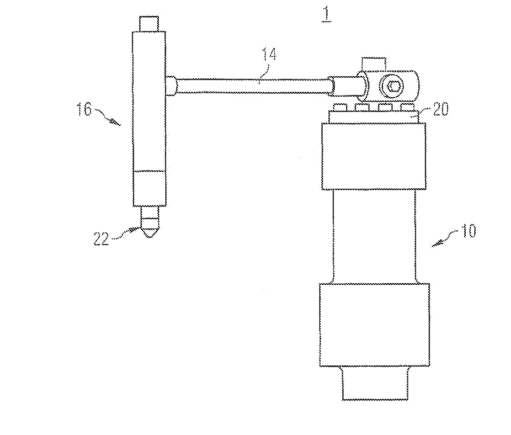
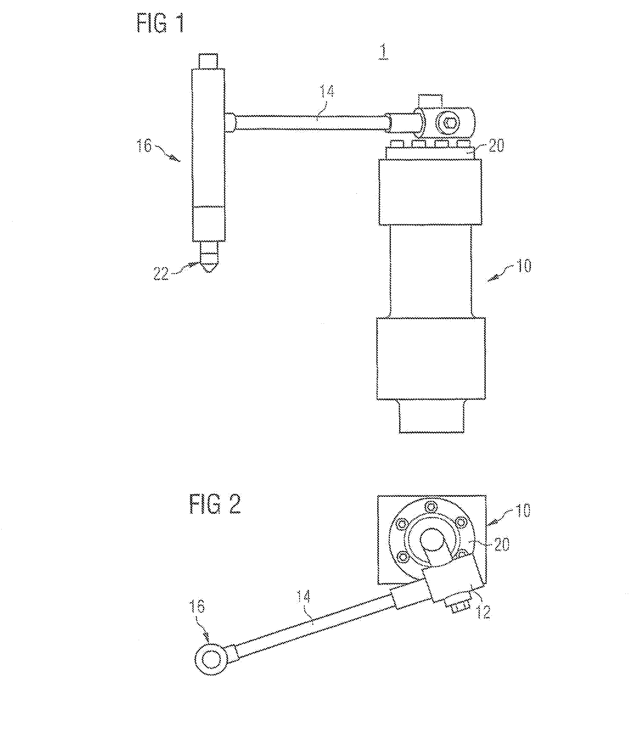
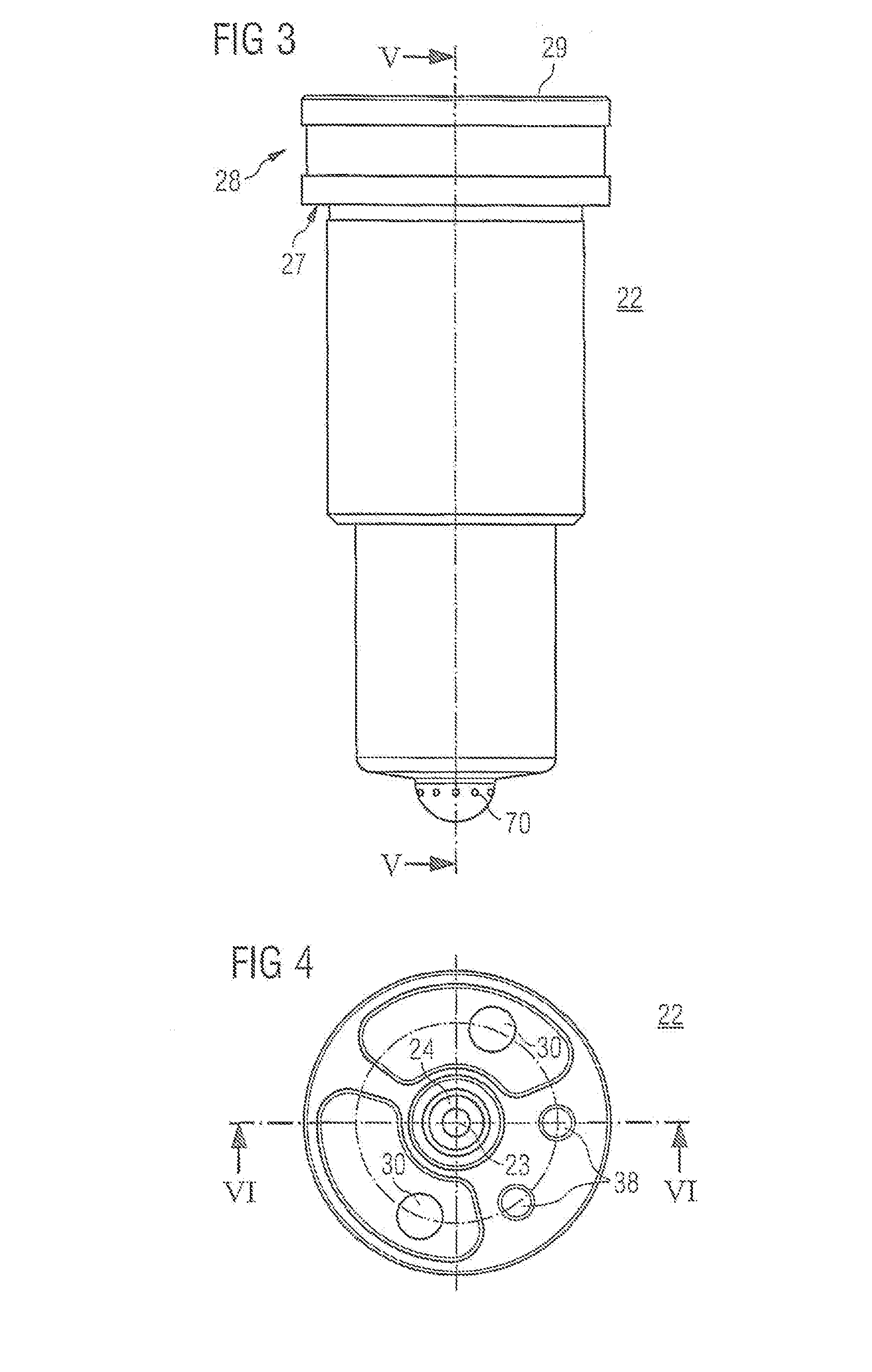
This patent describes an injection nozzle for a fuel injection system of an engine that has a sealing face to connect to the system, a needle guiding bore to control the movement of the needle, and a high pressure fuel chamber to manage fuel pressure. The design also reduces cavitation and flow force, which can increase the lifespan of the components.

Problems solved by technology

The operation of internal combustion engines with alternative fuels may result in strong wear of those components of the fuel injection systems that are in contact with the alternative fuel.
Specifically, fuel injection systems may be affected by the increased cavitation activity caused by an increased water content of alternative fuels.
Moreover, alternative fuels and low-sulphur fuels can have poor or completely missing lubrication properties and usually comprise small size particles in the range of, for example, 0.1-5 μm.
Due to the chemical composition and the physical properties of alternative fuels, alternative fuels may have an increased cavitation and corrosion activity and increase the wear of the components of the fuel system.

Method used


Image

  • Injection nozzle
  • Injection nozzle
  • Injection nozzle

Examples


Embodiment Construction

[0029]The following is a detailed description of exemplary embodiments of the present disclosure. The exemplary embodiments described therein and illustrated in the drawings are intended to teach the principles of the present disclosure, enabling those of ordinary skill in the art to implement and use the present disclosure in many different environments and for many different applications. Therefore, the exemplary embodiments are not intended to be, and should not be considered as, a limiting description of the scope of patent protection. Rather, the scope of patent protection shall be defined by the appended claims.

[0030]The present disclosure is based on the realization that engines operated with fuels, which may have an increased cavitation activity, may be prone to a shortening of the lifetime of respective components of the fuel injection system due to increased surface wear and damaging. An increase in surface wear may be in particular the case for components when the fuel is...


PUM


Abstract

An injection nozzle is disclosed. The injection nozzle may have a sealing face providing a sealed connection to the nozzle holder. The injection nozzle may also have a needle guiding bore. The needle guiding bore may have a nozzle holder section extending through the sealing face. The needle guiding bore may further have an injection side section fluidly connected to an outside of the injection nozzle via a plurality of nozzle spray holes. The needle guiding bore may also have a high pressure fuel chamber disposed between the nozzle holder section and the injection side section. The injection nozzle may also have a high pressure supply bore extending through the sealing face and fluidly and connect an opening in the sealing face with the high pressure fuel chamber via an extension.

Description

TECHNICAL FIELD[0001]The present disclosure generally refers to fuel injection systems of internal combustion engines and more particularly to injection nozzles of such fuel injection systems.BACKGROUND[0002]The operation of internal combustion engines with alternative fuels may result in strong wear of those components of the fuel injection systems that are in contact with the alternative fuel. Specifically, fuel injection systems may be affected by the increased cavitation activity caused by an increased water content of alternative fuels.[0003]Alternative fuels include, for example, first generation biofuels (for example: palm oil, canola oil, oils based on animal fat) and second generation biofuels (for example: oils made of non food corps, i.e. waste biomass). Examples of second generation biofuel include “pyrolysis oils” obtained from the pyrolysis of, for example, wood or agricultural wastes, such as the stalks of wheat or corn, grass, wood, wood shavings, grapes, and sugar c...

Claims


Application Information

Patent Timeline
IPC IPC(8): F02M61/14F02M61/18
CPCF02M61/18F02M61/14F02M55/008F02M61/10F02M61/168F02M2200/95F02M2200/03F02M2200/02F02M2200/04
Inventor VON DER OSTEN-SACK, ANDREASOHRT, OLE
Owner CATERPILLAR MOTOREN
Learn More