Fuel separation system for reducing parasitic losses

a separation system and fuel separation technology, applied in the direction of machines/engines, combustion air/fuel air treatment, electric control, etc., can solve the problems of parasitic losses in the vehicle, vehicle owners may not be willing to fill the vehicle with two types of fuel, etc., to improve engine performance and/or fuel economy, the effect of reducing the possibility of engine knock

Active Publication Date: 2015-04-30
FORD GLOBAL TECH LLC
View PDF9 Cites 17 Cited by
  • Summary
  • Abstract
  • Description
  • Claims
  • Application Information

AI Technical Summary

Benefits of technology

[0003]An engine may be supplied different types of fuel during different engine operating conditions to enhance engine performance and/or fuel economy. For example, an engine may be supplied gasoline via a first fuel injector and ethanol via a second fuel injector. Gasoline may be the sole fuel supplied to the engine at lower engine loads where the possibility of engine knock may be reduced.

Problems solved by technology

However, vehicle owners may not be willing to fill a vehicle with two types of fuel to obtain the benefits of operating an engine with two distinct and separate fuels.
After the fuels are separated the fuels may be

Method used


Image

  • Fuel separation system for reducing parasitic losses
  • Fuel separation system for reducing parasitic losses
  • Fuel separation system for reducing parasitic losses

Examples


Embodiment Construction

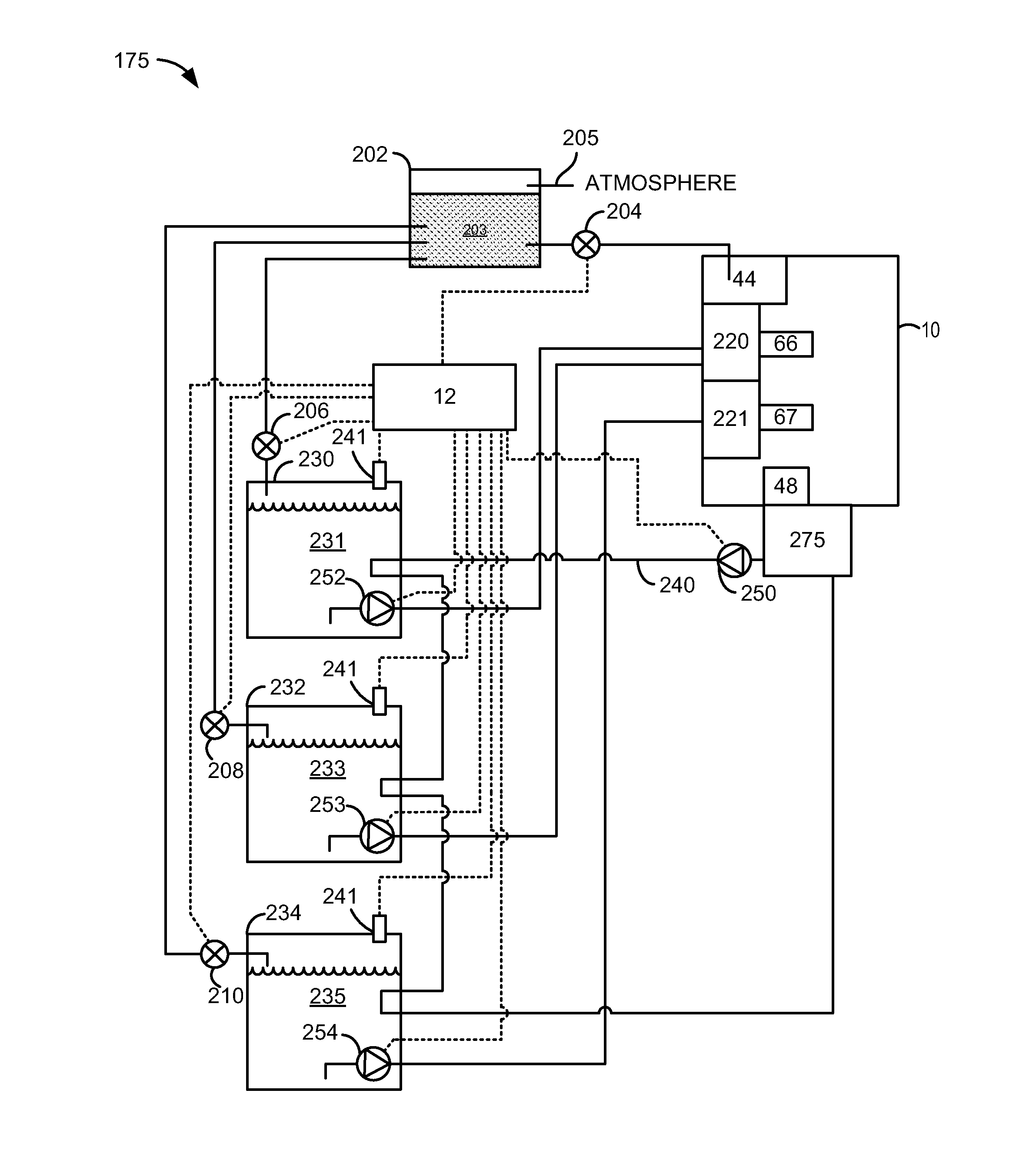
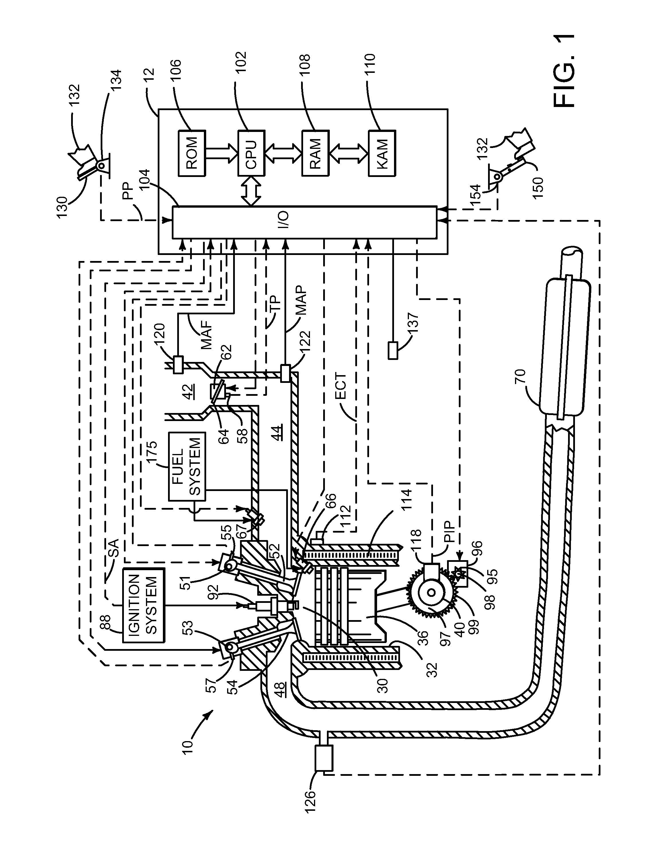
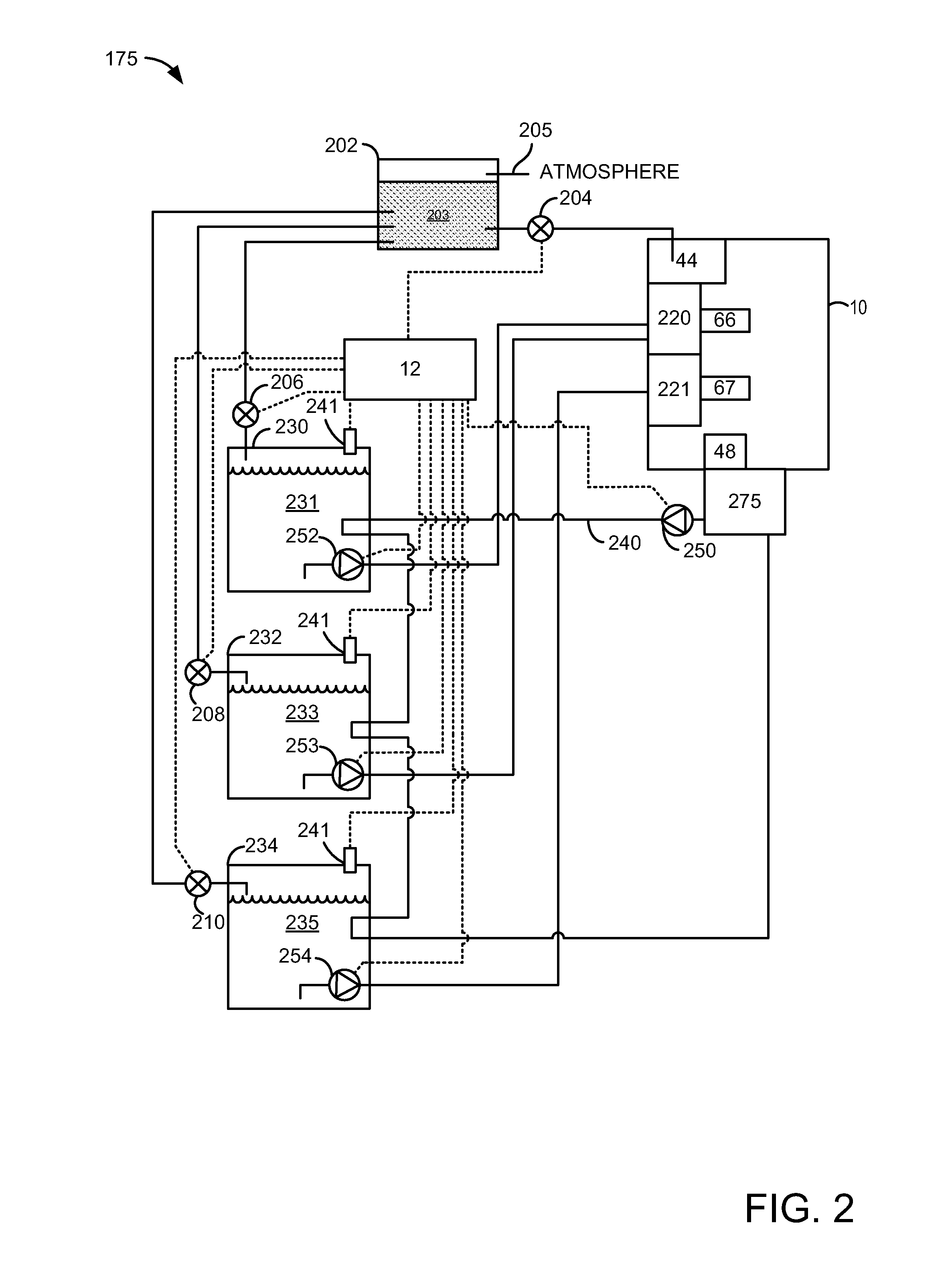
[0014]The present description is related to controlling fuel vapors of a vehicle. The fuel vapors may be used in an engine as shown in FIG. 1. The engine may be supplied fuel from one or more fuel tanks as shown in the fuel systems of FIGS. 2 and 3. Component fuels may be separated from a fuel mixture comprising two or more fuels via diurnal heating and cooling of vehicle fuel systems. The vehicle fuel systems may be arranged to allow higher octane fuel vapors to condense only in a higher octane fuel tank so that the possibility of unintended fuel mixing may be reduced. The method of FIG. 4 operates the vehicle fuel system in a way that reduces the possibility of mixing fuels via the evaporative emissions section of the vehicle fuel system.

[0015]Referring to FIG. 1, internal combustion engine 10, comprising a plurality of cylinders, one cylinder of which is shown in FIG. 1, is controlled by electronic engine controller 12. Electrical connections between controller 12 and the various...


PUM


Abstract

Systems and methods for separating higher octane fuel from a fuel mixture are presented. In one example, higher octane fuel is separated from lower octane fuel and allowed to condense in a fuel tank holding higher octane fuel so that parasitic engine losses are not increased by having to separate higher octane fuel from lower octane fuel a second time. The approach may be applied to fuel systems that include multiple fuel tanks storing different types of fuel.

Description

FIELD[0001]The present description relates to a system and methods for reducing parasitic losses that may be associated with separating a fuel mixture into its component fuels.[0002]The methods may be particularly useful for engines that operate on more than one fuel type.BACKGROUND AND SUMMARY[0003]An engine may be supplied different types of fuel during different engine operating conditions to enhance engine performance and / or fuel economy. For example, an engine may be supplied gasoline via a first fuel injector and ethanol via a second fuel injector. Gasoline may be the sole fuel supplied to the engine at lower engine loads where the possibility of engine knock may be reduced. As engine load increases, ethanol begins to be supplied to the engine in increasing amounts. Ethanol is also supplied as a greater fraction of fuel provided to the engine so that the possibility of engine knock may be reduced. However, vehicle owners may not be willing to fill a vehicle with two types of f...

Claims


Application Information

Patent Timeline
IPC IPC(8): F02M25/08
CPCF02M25/0872F02M37/0088F02M25/089F02D19/0649F02D19/0655F02D19/0692F02D19/081F02D19/0668F02D41/0025F02D41/0032Y02T10/30
Inventor LEONE, THOMAS G.ANDERSON, JAMES ERIC
Owner FORD GLOBAL TECH LLC
Why Eureka
Try Eureka