Liquid filler using single motive force

a single motive force and filler technology, applied in the direction of liquid handling, packaging goods, transportation and packaging, etc., can solve the problems of degraded performance capabilities, machine versatility and flexibility, and inability to match the performance of other known and described container filling methods

Inactive Publication Date: 2015-04-30
ODEN MACHINERY
View PDF0 Cites 22 Cited by
  • Summary
  • Abstract
  • Description
  • Claims
  • Application Information

AI Technical Summary

Benefits of technology

[0015]The subject matter of the present disclosure includes a filling machine for dosing and containers that eliminates the requirement for an expensive duplicate dosing pump and associated apparatus for each filling head of the machine. A single master dose pump is supplied with the liquid to be filled by a single outlet reservoir or by a single flow source liquid supply. A single master dose pump may operate as the single motive force to provide a master dose which is hydraulically subdivided into a plurality of equal subdoses. The single master dose pump may be a positive displacement pump that is adjustable in liquid flow rate in order to establish the desired rate of liquid flow through the entire liquid flow pathway of the apparatus and into the plurality of containers to be filled. In the liquid filling method and apparatus, the entire liquid flow pathway, from the master dose pump liquid supply to the plurality of liquid filling heads, when in operable condition, may be entirely hydraulic or liquid filled. The master dose provided by the master dose pump may be displaced into a liquid product dose distributor. The dose distributor hydraulically subdivides the master dose into a plurality of approximately equal subdoses, each of which is delivered into one of a plurality of subdose flow branches.

Problems solved by technology

This is because the range of usage and utility, termed machine versatility and flexibility, cannot be rivaled in performance by the other known and described container filling methods.
This method exhibits multiple positive displacement (PD) pump complexities and degraded performance capabilities, and requires a dose defining flow meter in each flow branch, negating much of the substantial cost reduction over the known and accepted multi-pump method.
The result of the described conventional and known in-line filler machine architecture or layout is a machine with a high degree of complexity which is directly proportional to the number of filling positions, and a cost which is related to the number of filling positions.

Method used


Image

  • Liquid filler using single motive force
  • Liquid filler using single motive force
  • Liquid filler using single motive force

Examples


first embodiment

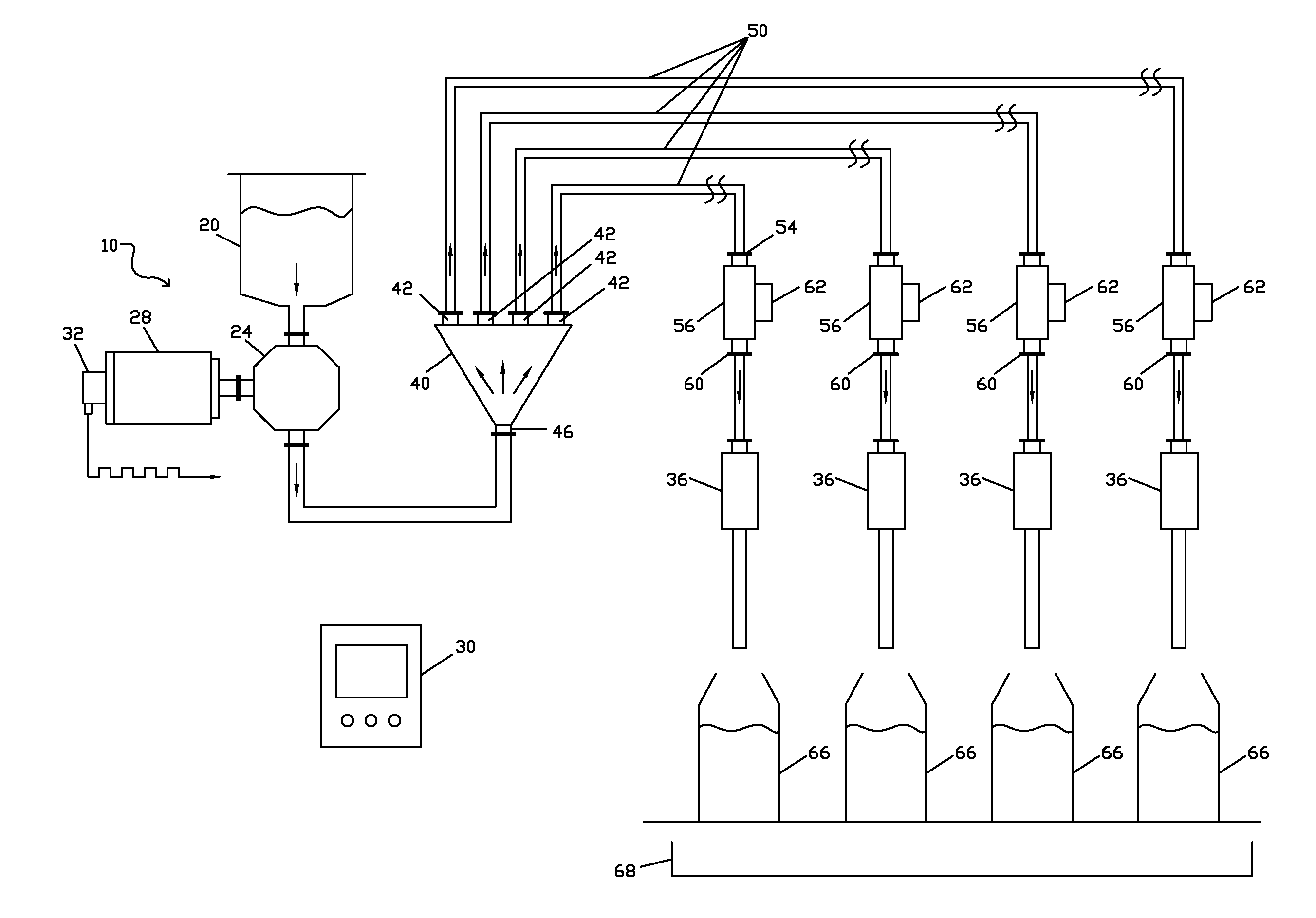
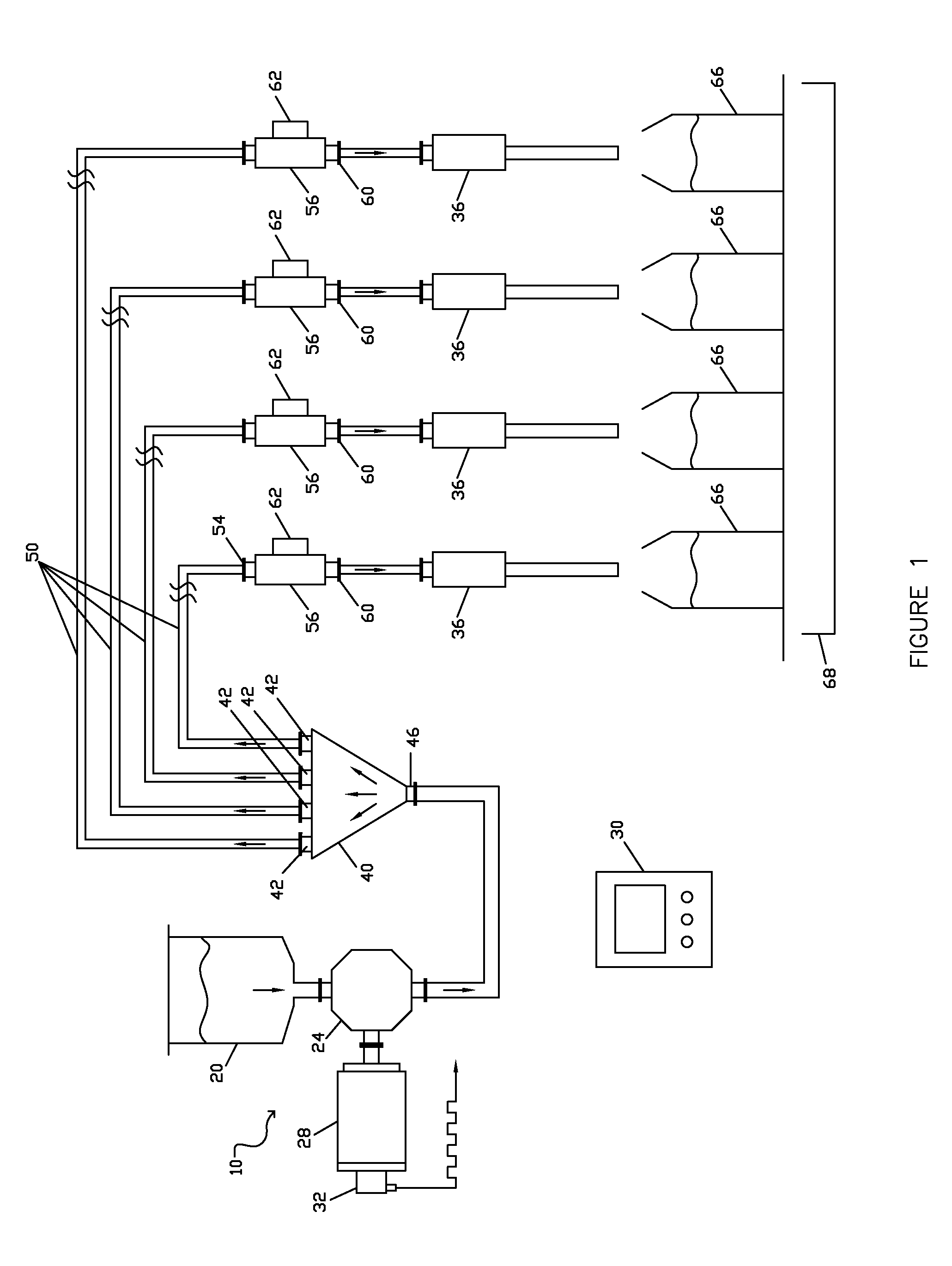
[0064]A first embodiment is disclosed in FIG. 1, and generally indicated by reference numeral 10. A liquid supply source, generally a supply reservoir 20, may be suitably sized to accommodate outflow demand and may be located proximate to the master dose pump 24. The supply reservoir 20 may be supplied with a suitable level control device (not illustrated) to allow for resupply from a bulk source. The supply can alternatively be a flow conduit from a remote bulk supply of the liquid to be dispensed.

[0065]The supply reservoir 20 is hydraulically connected to the master dose pump 24. The master dose pump 24 may be a positive displacement pump, and may be of any suitable positive displacement type. Some examples include linear piston pumps, and rotary lobe, gear and circumferential piston types. Progressive cavity, sine rotor, peristaltic, vane and diaphragm pumps may also be used.

[0066]The master dose pump 24 may be driven by an electric servo motor 28. Servo motor 28 may be rotary or...

second embodiment

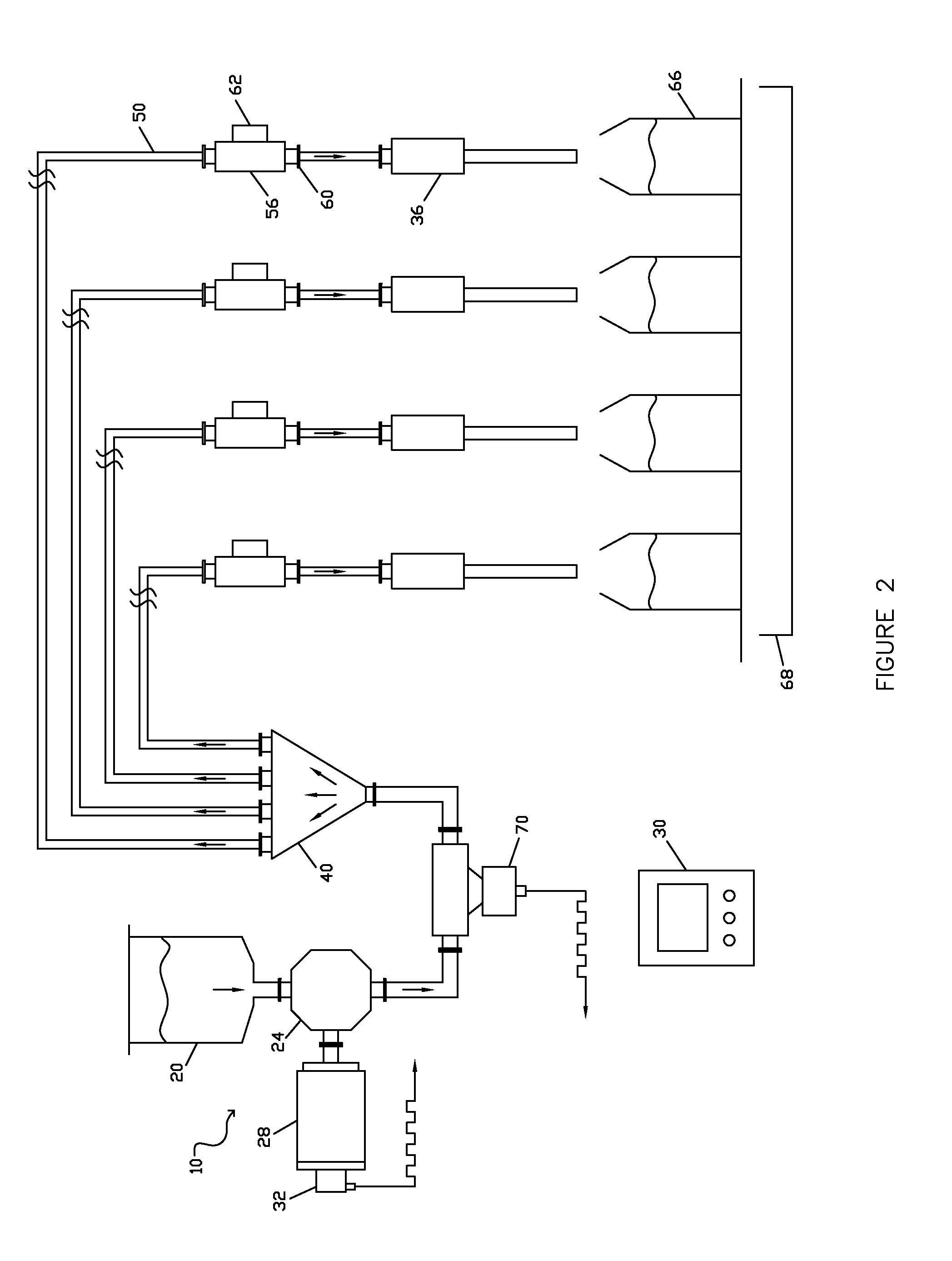
[0087]In a second embodiment, shown in FIG. 2, a liquid flow meter 70 is positioned in the liquid flow pathway between the outfeed of the master dose pump 24, and the liquid entry 46 of the dose distributor 40. The flow meter 70 may be a volumetric flow meter, such as a magnetic flow meter or another type of volumetric flow meter. Alternatively, the flow meter 70 may be a mass flow meter, such as a Coriolis mass flow meter or another type of mass flow meter.

[0088]When using a volumetric flow meter 70, master dose pump 24 provides the single motive force for liquid flow through the dosing apparatus, but does not define the volumetric master dose. Instead, the volumetric master dose is defined by the flow meter 70, generally as a pulse train output. In some cases, the master dose pump encoder pulses are counted and compared with the flow meter pulse count on a dose cycle by dose cycle basis as a means of providing checking, verification and validation of performance of the volumetric ...


PUM

PropertyMeasurementUnit
lengthaaaaaaaaaa
mass flow meteraaaaaaaaaa
massaaaaaaaaaa

Abstract

A dosing method and apparatus for filling containers in an automatic in-line or linear liquid filling machine where a single positive displacement dosing apparatus produces a repeatable volumetric or net weight master dose which is precisely subdivided hydraulically into a plurality of equal and repeatable subdoses. Each equal subdose synchronously fills a container such that with each dosing apparatus cycle all containers are simultaneously and equally filled. A precision dose control is located in each subdose flow branch.

Description

TECHNICAL FIELD[0001]The present invention relates generally to liquid dosing of containers and more particularly, a dosing apparatus for producing highly accurate and repeatable dose amounts for precisely filling containers using only a single motive force to produce the doses such that with each dosing apparatus cycle all containers are substantially simultaneously and equally filled.BACKGROUND OF THE INVENTION[0002]Liquid filling machines of many types and categories are well known in the patent arts and in commercial practice. One broad category of automatic liquid fillers is termed the in-line or linear liquid filler.[0003]In terms of container motion through the machine, in-line filler types may be of intermittent container motion or continuous container motion, although the former greatly dominate in usage. With continuous motion types, containers are filled in groups, corresponding to the number of filling positions, as containers move continuously from the infeed of the mac...

Claims


Application Information

Patent Timeline
Patent Type & Authority Applications(United States)
IPC IPC(8): B67C3/28B67C3/22B67C3/00
CPCB67C3/287B67C3/007B67C3/225B67C3/20B67C3/288
Inventor PHALLEN, IVER
Owner ODEN MACHINERY
Why Eureka
Try Eureka