
Apparatus to Reduce Pressure and Thermal Sensitivity of High Precision Optical Displacement Sensors

a technology of optical displacement sensor and apparatus, which is applied in the direction of interferometer, instruments, borehole/well accessories, etc., can solve the problems of limited performance and the operational size of the displacement sensor, and limit the performance and magnetic based displacement sensor

Active Publication Date: 2015-04-30
BAKER HUGHES INC
View PDF5 Cites 15 Cited by
  • Summary
  • Abstract
  • Description
  • Claims
  • Application Information

AI Technical Summary

Benefits of technology

This patent is about a method for estimating a parameter of interest in an earth formation intersected by a borehole using an optical displacement device. The device generates information based on its relative motion between reflective surfaces, which is indicative of the parameter of interest. To compensate for changes in the device due to factors like temperature and pressure, the information is adjusted by adjusting the light source or using a device that has a fixed reflective surface and a variable gap between its surfaces. This method ensures accurate estimation of the parameter of interest in the earth formation.

Problems solved by technology

These electrical and magnetic based displacement sensors may be limited due to one or more of: low sensitivity, the need for high-voltage biasing, poor electrical isolation, environmental factors, and response nonlinearities.
These limitations may require a close coupling between transducer design and the sensor mechanical design, which may limit performance and the operational size of the displacement sensor.

Method used


Image

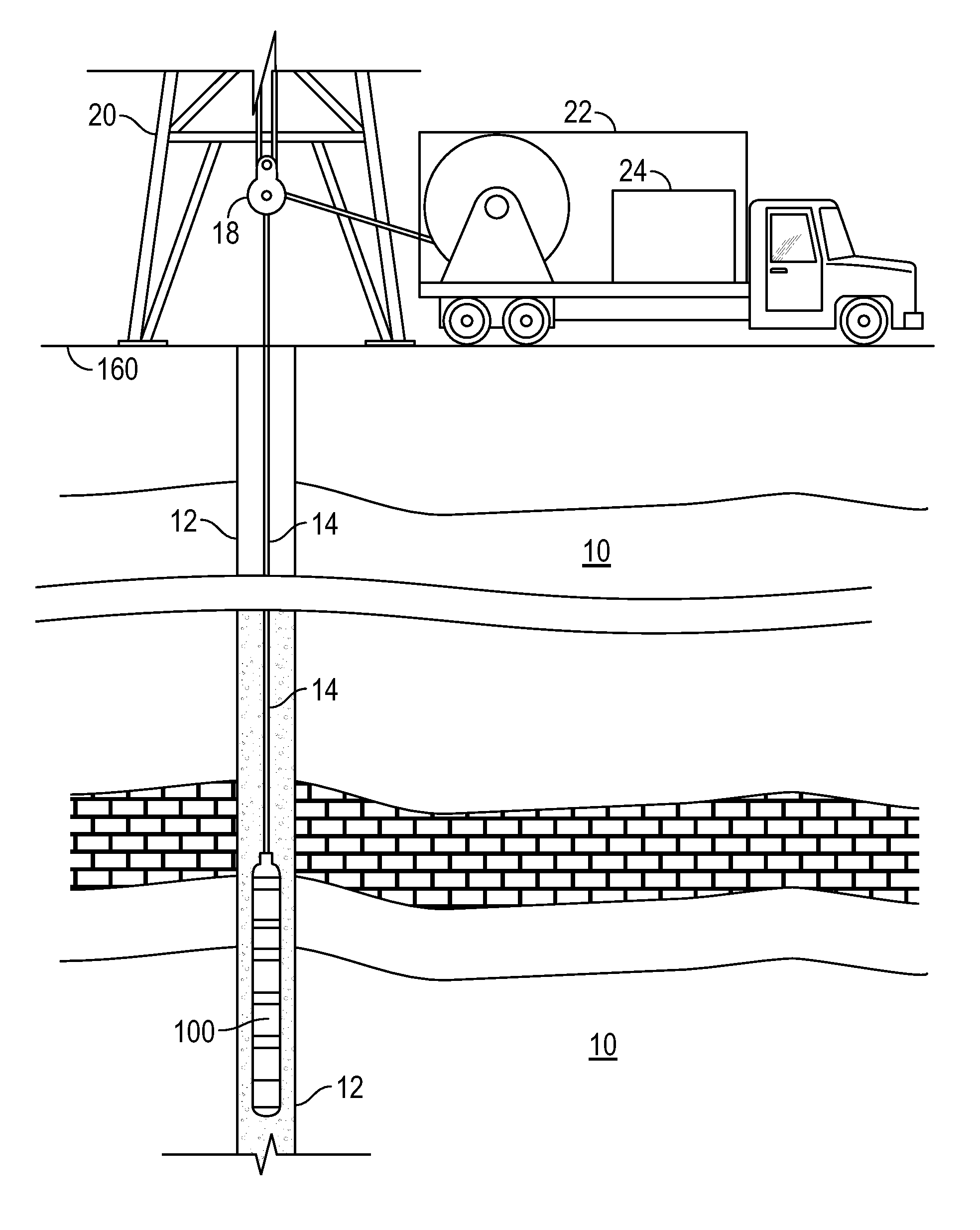
  • Apparatus to Reduce Pressure and Thermal Sensitivity of High Precision Optical Displacement Sensors
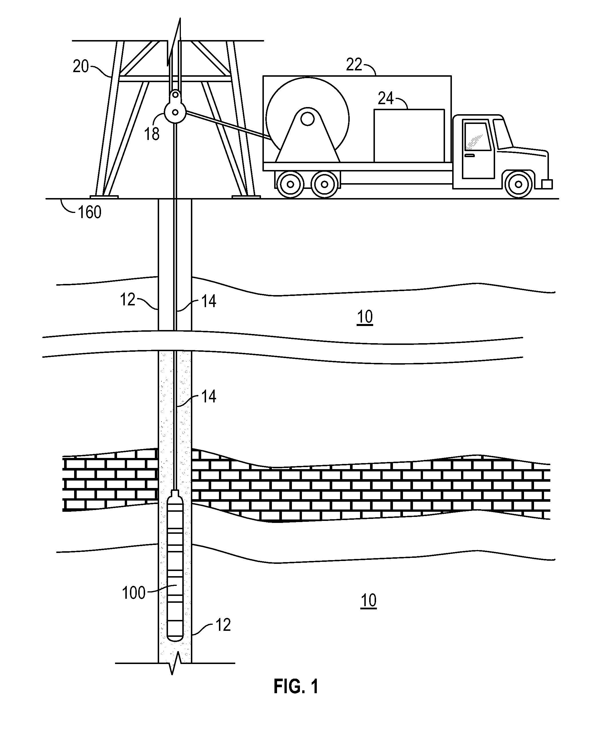
  • Apparatus to Reduce Pressure and Thermal Sensitivity of High Precision Optical Displacement Sensors
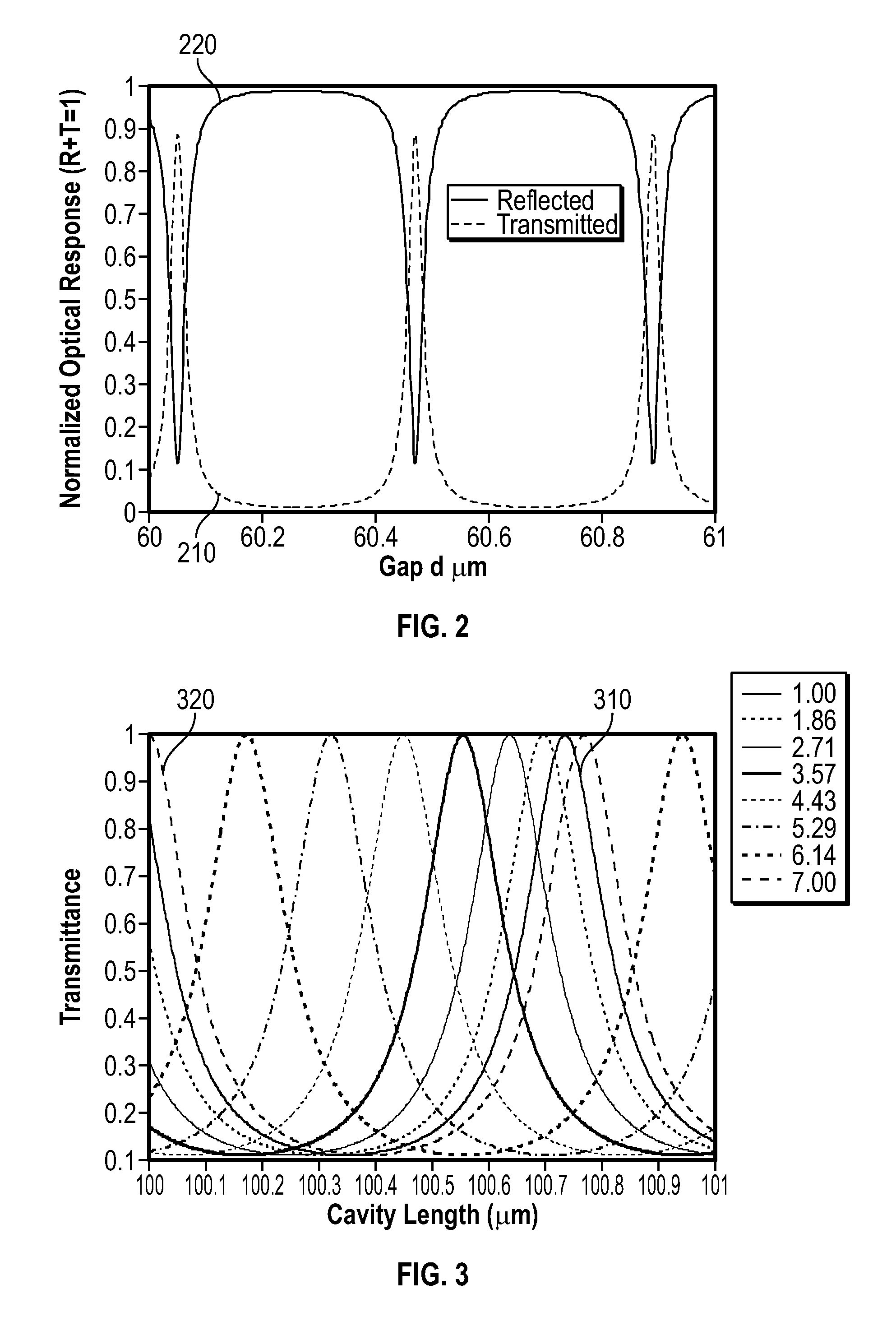
  • Apparatus to Reduce Pressure and Thermal Sensitivity of High Precision Optical Displacement Sensors

Examples


Embodiment Construction

[0023]The present disclosure relates to devices and methods for estimating a parameter of interest with an optical displacement device using techniques for preventing changes in the information generated in the optical displacement device resulting from temperature or pressure changes at the optical displacement device. These techniques may include compensating for the changes at the optical displacement device.

[0024]Aspects of the present disclosure include a dual-cavity optical displacement device. In traditional gravimeters, the cavity length may fluctuate with temperature, producing an offset term which is accounted for in measurement calculations. By using a common member to support a reflective surface for each respective cavity on opposing sides, measurements from the two devices may be related to one another, such that effects of temperature changes on one cavity cancel the effects of the temperature changes on the other cavity. The cavities of the dual-cavity gravimeter may...


PUM


Abstract

Methods, systems and devices for estimating a parameter of interest in a borehole. The method may include generating information from an optical displacement device relating to relative motion between two or more reflective surfaces thereof that is indicative of the parameter of interest; and preventing changes in the information resulting from changes at the optical displacement device in at least one of i) temperature, or ii) pressure, by compensating for the changes. Compensating may include adjusting at least one light source generating an electromagnetic beam at least partly received by the optical displacement device responsive to information relating to a control optical displacement device at the optical displacement device. Compensating may include using an optical displacement device and configuring the optical displacement device such that a difference between a first variable gap and a second variable gap is substantially zero while the apparatus is subject to nominal conditions.

Description

BACKGROUND OF THE DISCLOSURE[0001]1. Field of the Disclosure[0002]In one aspect, this disclosure generally relates methods and apparatuses for sensing displacement optically.[0003]2. Background of the Art[0004]Displacement sensors, such as microphones and pressure sensors, are well-known. Many displacement sensors may be based on one or more of electrical capacitance, electrical impedance, or magnetic fields. These electrical and magnetic based displacement sensors may be limited due to one or more of: low sensitivity, the need for high-voltage biasing, poor electrical isolation, environmental factors, and response nonlinearities. These limitations may require a close coupling between transducer design and the sensor mechanical design, which may limit performance and the operational size of the displacement sensor. Optical displacement sensors, such as displacement sensors using an etalon, may be electrically and magnetically insensitive, which may mitigate limitations found in elec...

Claims


Application Information

Patent Timeline
Patent Type & Authority Applications(United States)
IPC IPC(8): G01B11/14G01V8/10
CPCG01V8/10G01B11/14G01V11/00G01D5/266G01D5/34G01D5/35312E21B47/017G01N21/01G01B2290/25E21B49/00G01B9/02052G01B9/02067G01B9/02075
Inventor EDWARDS, CARL M.
Owner BAKER HUGHES INC
Learn More