Flexible Wrist-Worn Recharging Device

a rechargeable device and wrist-worn technology, applied in the direction of electric winding, instruments, horology, etc., can solve the problems of minor inconvenience, unable to recharge, and render useless, so as to maximize solar exposure, increase power supply, and maximize the potential surface area exposure to the sun and electricity generation potential

Inactive Publication Date: 2015-04-30
VANCE LUKE ALAN
View PDF10 Cites 31 Cited by
  • Summary
  • Abstract
  • Description
  • Claims
  • Application Information

AI Technical Summary

Benefits of technology

[0020]The preferred embodiment of said invention exhibits flexibility characteristics enabling the user to lay a wrist-worn electrical storage device to maximize solar exposure when fully extended. The flexible nature of the apparatus enables the full extension of the device, thus maximizing the potential surface area exposure to the sun and the electricity generation potential of the unit. Furthermore, the preferred embodiment of the invention enables the user to link said potential device in series with other power sources, including other wrist-worn electrical storage devices such as those described herein, to provide increased power supply to a depleted Mobile Electronic Device and / or to coordinate recharge of the Battery-Bank with the battery of said Mobile Electronic Device.
[0021]Further, the preferred embodiment of the invention additionally or alternatively enables the use of a wrist-worn electrical storage device with an existing Mobile Electronic Device, such as a smart-watch, to prolong the effective battery life of such a device.

Problems solved by technology

As a result, a depleted battery charge creates an undesirable situation that may cause inconvenience.
The inconvenience may be minor, such as an inconvenience that relates to tardiness to a meeting or loss of income from missed business opportunities.
However, the inconvenience may be more major, such as an inconvenience interfering with communication in emergency situations or other negative scenarios.
However, several problems generally associate with such items.
This generally renders them useless after the electrical power stored in such devices has been depleted before the user is able to use another power source such as a wall outlet, automobile accessory port or secondary computing device to replenish the charge.
The problem with this strategy to charging a Battery-Bank with the surface area of a watch face or watch housing is that the area provided is not sufficient to supply the needs of a Mobile Electronic Device.
Thus, a watch face charging device as known in the prior art lacks the effective area for recharging such a Battery-Bank unless the watch face is impractically large.
Although such prior art items attempts to solve problems associated with lacking surface area by maximizing or extending available surface area able to collect solar energy to provide recharging power to an integrated Battery-Bank, such items generally fail to account for the point source characteristics of the provided solar energy.
As a result, such items in the prior art are not able to use the full solar collection potential of the maximized array surface area.
Typical items in the prior art do not allow for such wearable solar array enabled Battery-Banks to be recharged from an alternate power source such as a home power outlet or vehicle accessory power port while simultaneously providing pass-thru power to the Mobile Electronic Device.
Items in the prior art do not enable the serial connection of such items, commonly referred to as “Daisy-Chaining,” to effectively provide a singular Battery-Bank of higher voltage and output capacity for a faster and / or more effective recharge to the Mobile Electronic Device.
Furthermore, the items available in the prior art do not allow for the accessory use of a supplemental power source and / or supplemental power generation with existing wearable technology such as a battery enabled wrist-band to be integrated with a discrete existing product such as a smart-watch.

Method used


Image

  • Flexible Wrist-Worn Recharging Device
  • Flexible Wrist-Worn Recharging Device
  • Flexible Wrist-Worn Recharging Device

Examples


Embodiment Construction

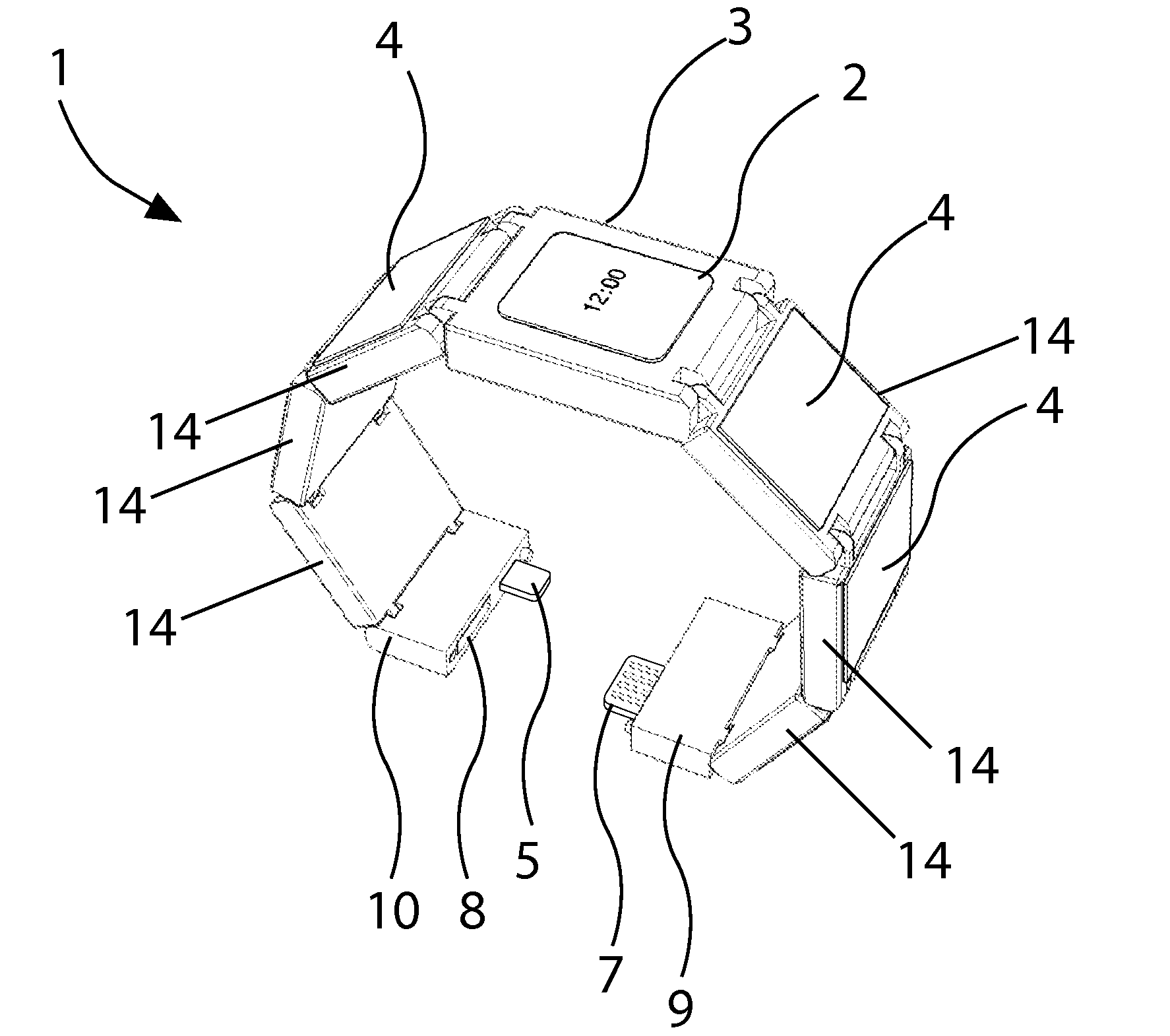
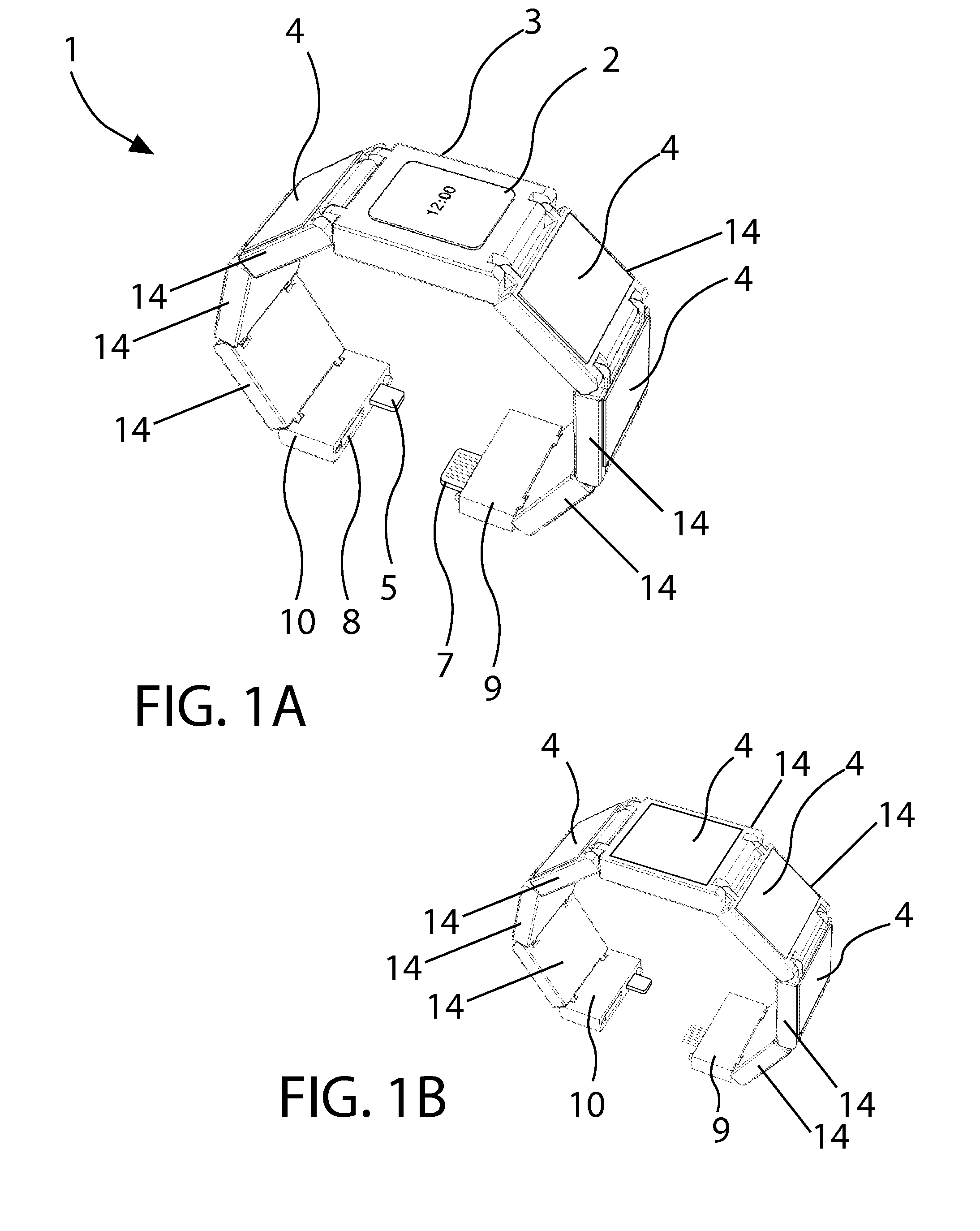
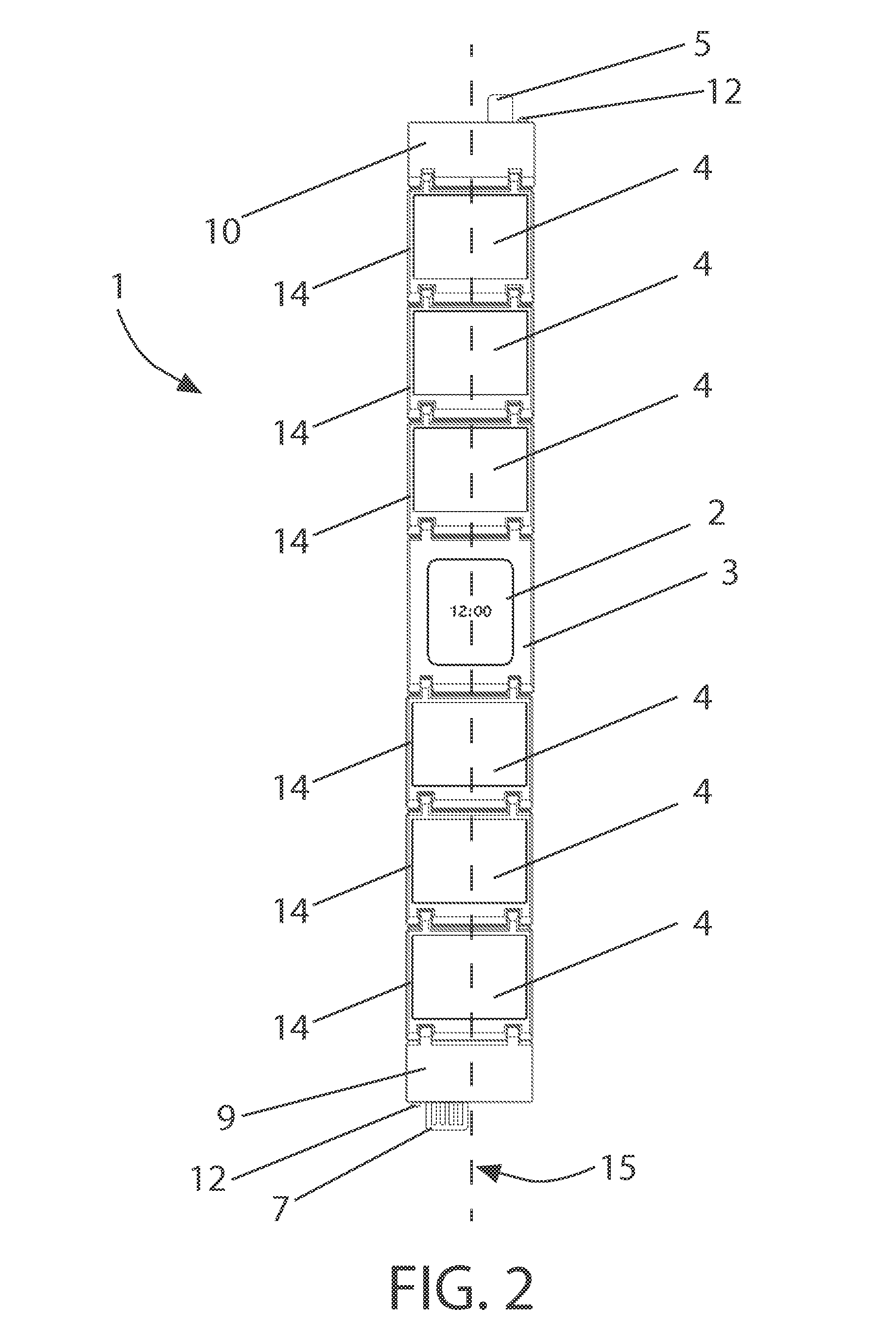
Integrating with Smart-Watch[0053]20. Inductive Charging Surface

DETAILED DESCRIPTION

[0054]Mobile Electronic Devices, including smart-phones, require a minimum of 500 mA and stable 5V before accepting charge current. Therefore (0.5 A×5V=2.5 W) a 2.5 W power source is required to charge smart-phones. Many 3.7V-4.2V batteries can provide a stable 5V output when wired to a DC voltage regulator. However, the battery must be capable of providing a minimum output rate of 500 mA. The preferred embodiment of the invention incorporates battery size specifications of a supplementing Battery-Bank in accordance with such needs.

[0055]Battery selection may be driven not only by voltage and capacity, but also by charge / recharge rate specifications. If the battery has a capacity of less than 500 mAh, then it must have a discharge rating or C-rate of higher than 1 if the target battery, or the battery to be recharged, requires a minimum of 500 mA for a recharge operation.

[0056]It will be appreciated ...


PUM


Abstract

An electrical storage device incorporating embodiments of the invention is capable of converting and/or storing energy provided by light-radiation and ancillary power sources for use intended to provide electrical charge to battery operated and Mobile Electronic Devices. The preferred embodiment of the invention exhibits a form of a Wrist-Worn Device comprising of a Battery-Bank, Photovoltaic Array and Controller. Typically in the form of a Flexible Wrist-Worn Recharging Device, the preferred embodiment of the invention may be an independent device connected to battery-operated devices such as a Mobile Electronic Device as needed, or otherwise integrated with exiting Mobile Electronic Devices to provide augmented battery life.

Description

[0001]CROSS-REFERENCE TO RELATED APPLICATIONS[0002]This application claims the benefit of U.S. Provisional Application 61 / 895,233 filed Oct. 24, 2013.STATEMENT REGARDING FEDERALLY SPONSORED RESEARCH OR DEVELOPMENT[0003]Not ApplicableREFERENCE TO SEQUENCE LISTING, A TABLE, OR A COMPUTER PROGRAM LISTING COMPACT DISK APPENDIX[0004]Not ApplicableBACKGROUND OF THE INVENTION[0005]A mobile technology-centric society exhibits an increasingly pervasive utilization of mobile electronic devices. Mobile technology has enabled a more efficient workplace, communication modes and execution of common everyday tasks. Such tasks include even mundane tasks such as identifying the most efficient route home or finding the nearest market. A requirement necessary to enable useful access to and ongoing usage of mobile devices is a portable and reliable energy supply. Due to increasing reliance upon Mobile Electronic Devices, mechanisms for portable electronic energy storage, back-up batteries and alternati...

Claims


Application Information

Patent Timeline
Patent Type & Authority Applications(United States)
IPC IPC(8): H02J7/00G04G19/00A44C5/00
CPCH02J7/0042G04G19/00A44C5/0061G04C10/02G04G17/083G04G21/00A44C5/105A44C5/2076
Inventor VANCE, LUKE ALAN
Owner VANCE LUKE ALAN
Why Eureka
Try Eureka