
Image forming apparatus

a technology of forming apparatus and forming tube, which is applied in the direction of electrographic process apparatus, printing, instruments, etc., can solve the problem of increasing costs by an amount, and achieve the effect of reducing unnecessary radiation and inexpensive cos

Active Publication Date: 2015-04-30
CANON KK
View PDF6 Cites 0 Cited by
  • Summary
  • Abstract
  • Description
  • Claims
  • Application Information

AI Technical Summary

Benefits of technology

The present invention is about a device that can make images while minimizing the amount of unnecessary radiation. This device is designed to be cheap and effective.

Problems solved by technology

Therefore, the costs will increase by an amount corresponding to the newly added clock generation circuit.

Method used


Image

  • Image forming apparatus
  • Image forming apparatus
  • Image forming apparatus

Examples


Embodiment Construction

[0053]Various exemplary embodiments, features, and aspects of the invention will be described in detail below with reference to the drawings. The description of the following exemplary embodiments is a mere example and does not intend to narrowly limit the scope of the present invention.

[0054][Image Forming Apparatus]

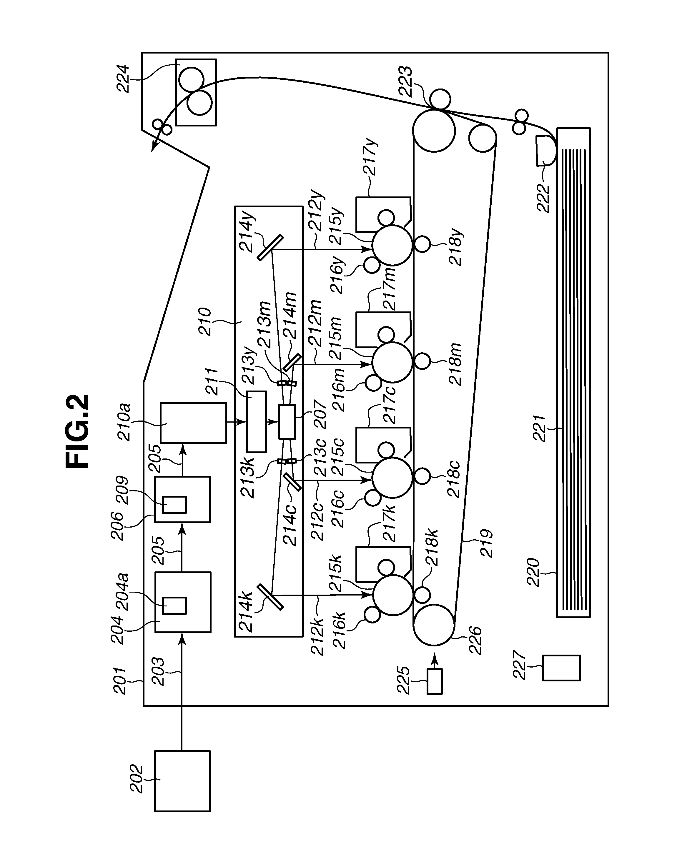
[0055]An image forming apparatus according to a first exemplary embodiment is described in detail below. FIG. 2 is a schematic cross-sectional view illustrating a configuration of a color laser beam printer 201 that is operable as the image forming apparatus according to the present invention. The image forming apparatus according to the present invention includes four color image forming units that can cooperatively form a color image by superposing four-color (Y: yellow, M: magenta, C: cyan, and Bk: black) images.

[0056]FIG. 3 is an enlarged view illustrating one image forming unit. Each image forming unit includes a photosensitive drum 215 (215y, 215m, 215c, or 215k) ...


PUM


Abstract

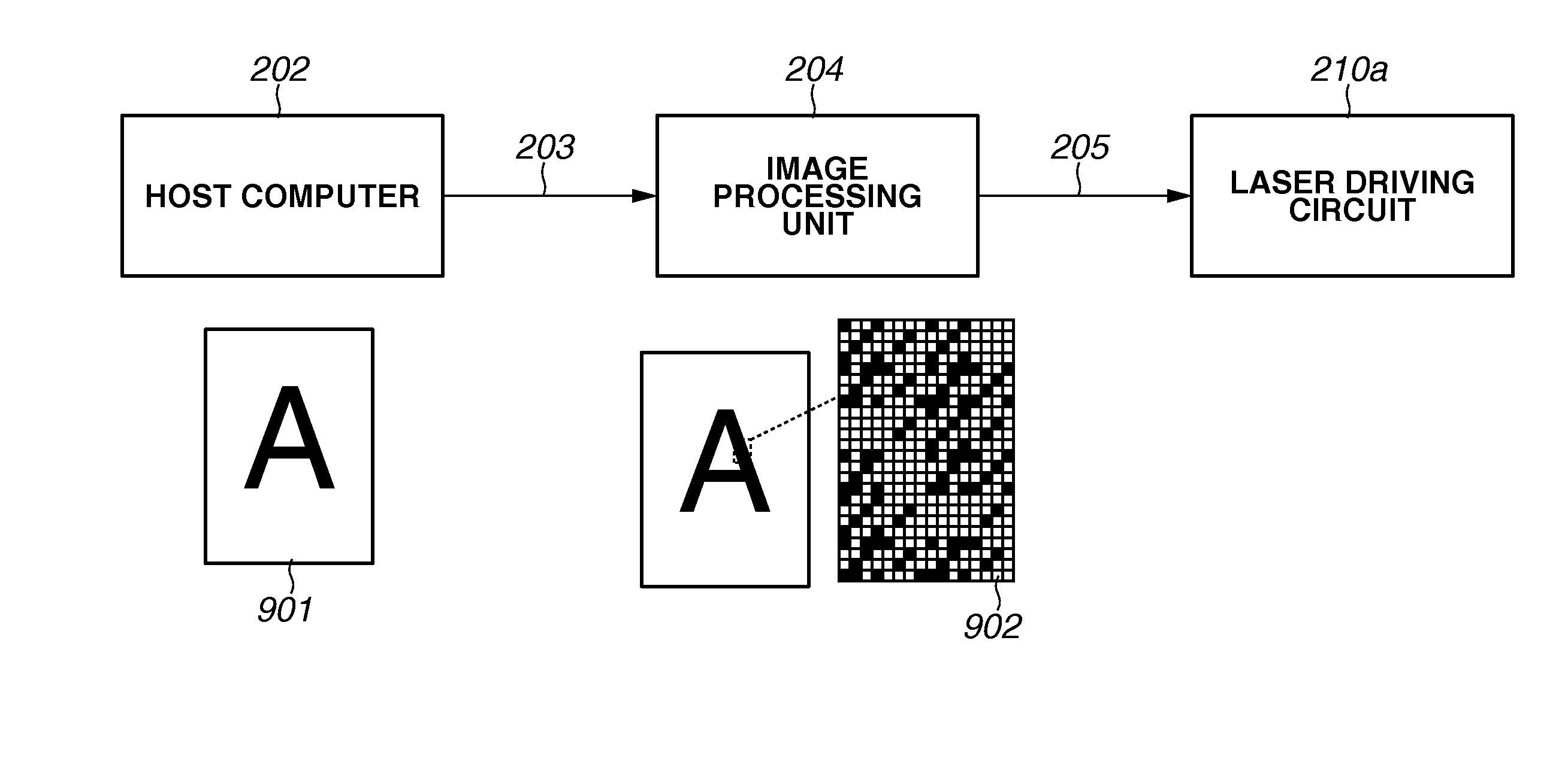
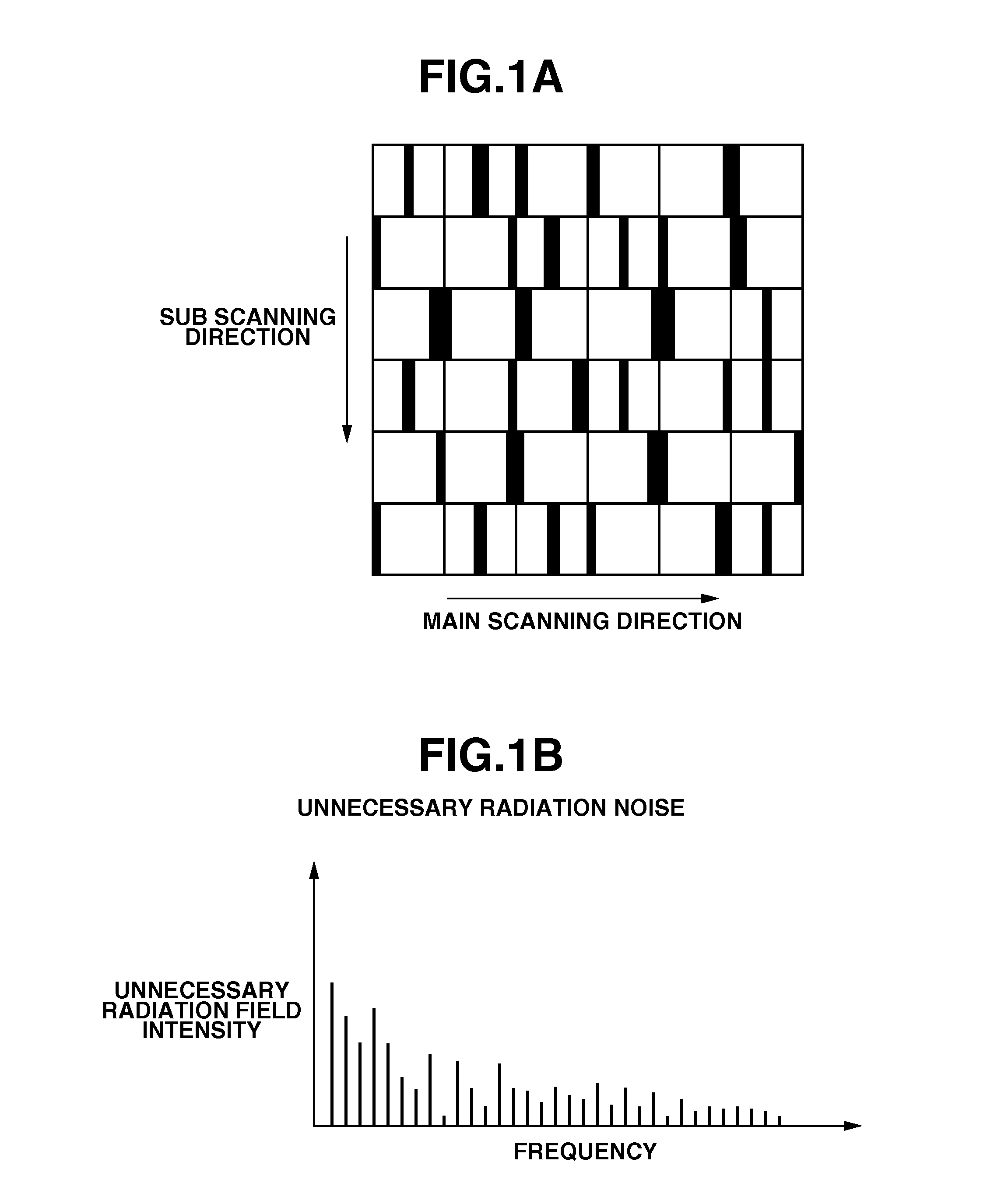
An image forming apparatus includes a signal generation unit configured to generate a light-emission signal. The signal generation unit stores information relating to a toner non-adherent area oriented light-emission pattern having been set beforehand. The toner non-adherent area oriented light-emission pattern is a light-emission pattern that causes a light irradiation unit to emit light in such a way as to prevent toner particles from adhering to a photosensitive member. When the light irradiation unit scans respective portions corresponding to two pixels adjacently disposed in a scanning direction a based on a part of the light-emission signal generated based on the toner non-adherent area oriented light-emission pattern, at least one of (a) light-emission start timing of light irradiation unit and (b) light-emission termination timing of the light irradiation unit is differentiated between the two pixels.

Description

BACKGROUND OF THE INVENTION[0001]1. Field of the Invention[0002]The present invention relates to an image forming apparatus (e.g., a color laser printer, a color copy machine, or a color facsimile) that performs an image forming operation including electrophotographic processes. In particular, the present invention relates to a technique which can reduce unnecessary radiations that may be emitted from the image forming apparatus.[0003]2. Description of the Related Art[0004]An electrophotographic color image forming apparatus forms a latent image by causing a light irradiation unit to irradiate a charged photosensitive member with light (i.e., perform an exposure operation), and forms a toner image on the photosensitive member by causing a developing device to adhere toner particles to the latent image on the photosensitive member.[0005]Usually, the light irradiation unit irradiates a limited area of the photosensitive member (i.e., a toner adherent area) with light. However, as disc...

Claims


Application Information

Patent Timeline
Patent Type & Authority Applications(United States)
IPC IPC(8): B41J2/385G09G3/32
CPCG03G15/043G03G2215/0431B41J2/473B41J2/442
Inventor WATANABE, SHINRISHIMIZU, YUSUKE
Owner CANON KK
Learn More