Antenna element, antenna unit and communication module

a technology of antenna elements and communication modules, applied in the direction of resonant antennas, independent non-interacting antenna combinations, antenna earthings, etc., can solve the problems of complex management of multiple kinds of antenna elements, increase in cost accompanying, and increase in production costs, so as to reduce unnecessary radiation, reduce the size of antenna elements, and reduce the effect of siz

Active Publication Date: 2018-10-11
MURATA MFG CO LTD
View PDF0 Cites 0 Cited by
  • Summary
  • Abstract
  • Description
  • Claims
  • Application Information

AI Technical Summary

Benefits of technology

[0043]According to the communication module, since the above-described antenna unit is included, it is possible support multiple frequency bands while reducing the size thereof and reducing unnecessary radiation.
[0044]According to preferred embodiments of the present invention, it is possible to provide antenna units that support multiple frequency bands while reducing the size thereof and reducing unnecessary radiation.

Problems solved by technology

However, since only a single band is used in a single wireless system in many cases, an antenna element is used only for a single band even in a wireless system, such as a communication module using a multiband-support IC.
Accordingly, at a manufacturer of the antenna element and a manufacturer manufacturing various devices containing the antenna element, the following problems may arise, for example.
That is, management of production, inventory control, and logistics of the antenna element, for example, are complicated, or reduction in an amount of production for each kind of antenna element, and an increase in cost accompanying these problems, and so on may arise.
In the related art, it is necessary to select positions and component values of the respective mounted components for adjusting the operating frequency, and therefore management of multiple kinds of antenna elements is complicated.
Further, mounting the components increases a height of an antenna portion, thus hindering a reduction in size.
In addition, it is difficult to optimize antenna characteristics, because radiation elements (radiation conductors) not functioning effectively in a frequency desired to be used are included, and thus, unnecessary radiation is caused, for example.

Method used


Image

  • Antenna element, antenna unit and communication module
  • Antenna element, antenna unit and communication module
  • Antenna element, antenna unit and communication module

Examples


embodiment 1

Preferred Embodiment 1

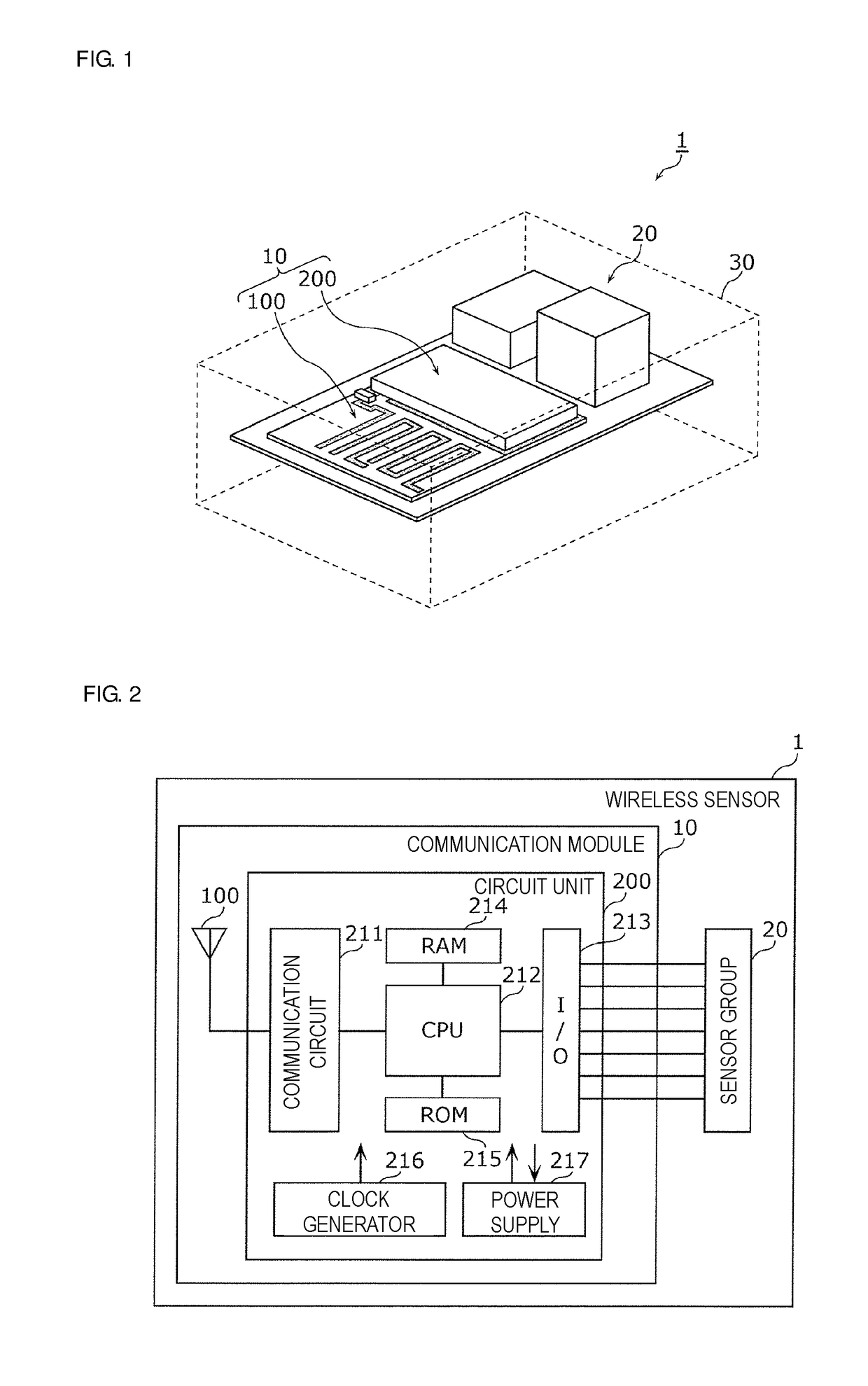
[0064]First, a configuration of a communication module will be described.

[0065]FIG. 1 is a perspective view illustrating a configuration of a wireless sensor 1 including a communication module 10 according to the present preferred embodiment. Additionally, FIG. 2 is a block diagram illustrating a functional configuration of the wireless sensor 1 including the communication module 10 according to the present preferred embodiment. Note that, in FIG. 1, elements arranged inside a housing 30 are illustrated, by seeing through the housing 30 of the wireless sensor 1. Additionally, hereinafter, although explanations will be provided with an upper side of a paper surface of FIG. 1 being an upside, the upper side of a paper surface may not be the upside depending on the particular use of the wireless sensor 1. Thus, the upper side of a paper surface of FIG. 1 is not limited to an upside of the wireless sensor 1.

[0066]The wireless sensor 1, for example, measures tempera...

modification 1

of Preferred Embodiment 1

[0115]In Preferred Embodiment 1, the radiation conductor 110 includes the radiation portions 111 to 113, and each of the radiation portions is the top surface portion. However, a radiation conductor may include bottom surface portions provided on a bottom surface of the antenna board AB. Accordingly, hereinafter, a communication module 10A according to Modification 1 of Preferred Embodiment 1 will be described using a communication module including the radiation conductor as an example. Note that, in the present modification, since a functional configuration of the communication module 10A is similar to Preferred Embodiment 1, description thereof is omitted.

[0116]FIG. 6 is a diagram illustrating an exemplary configuration of an antenna unit 100A according to Modification 1 of Preferred Embodiment 1. Specifically, (a) of FIG. 6 is a perspective view of the antenna unit 100A, and (b) of FIG. 6 is a cross-sectional view of main portions of (a) of FIG. 6. FIG. 7...

modification 2

of Preferred Embodiment 1

[0131]Although in Preferred Embodiment 1 and Modification 1 thereof, the antenna elements are configured to support three bands, it is sufficient that the antenna elements are configured to support two or more bands, and, for example, the antenna elements may preferably be configured to support four or more bands. Accordingly, hereinafter, a communication module 10B according to Modification 2 of Preferred Embodiment 1 will be described using a communication module including the antenna element as an example. Note that, in the present modification, since a functional configuration of the communication module 10B is similar to that of Preferred Embodiment 1, description thereof is omitted.

[0132]FIG. 9 is a diagram illustrating an exemplary configuration of an antenna unit 100B according to Modification 2 of Preferred Embodiment 1. Specifically, FIG. 9 is a perspective view of the antenna unit 100B. FIG. 10 is a top view of the antenna unit 100B according to M...


PUM


Abstract

An antenna element includes an antenna board, a radiation conductor including radiation portions including a top surface portion and being divided at positions corresponding to frequency bands and provided with respect to a first feeding point in plan view of the antenna board, through-conductors penetrating the antenna board at respective positions of end portions of the top surface portion in a thickness direction, and bottom surface electrodes provided on a bottom surface of the antenna board opposite the end portions of the top surface portion, and connected to the top surface portion via the through-conductors.

Description

CROSS REFERENCE TO RELATED APPLICATIONS[0001]This application claims the benefit of priority to Japanese Patent Application No. 2015-252525 filed on Dec. 24, 2015 and is a Continuation Application of PCT Application No. PCT / JP2016 / 079033 filed on Sep. 30, 2016. The entire contents of each application are hereby incorporated herein by reference.BACKGROUND OF THE INVENTION1. Field of the Invention[0002]The present invention relates to an antenna element mounted on a motherboard, and an antenna unit including the motherboard and the antenna element, and a communication module including the antenna unit.2. Description of the Related Art[0003]In wireless systems for IoT (Internet of Things), such as a sensor network system and a lighting control system, multiband-support for a transceiver IC (Integrated Circuit) has been developed. Accordingly, a single IC may be used in a wireless system capable of supporting multiple frequency bands. However, since only a single band is used in a singl...

Claims


Application Information

Patent Timeline
Patent Type & Authority Applications(United States)
IPC IPC(8): H01Q21/30H01Q1/38H01Q1/48H01Q9/26
CPCH01Q21/30H01Q1/38H01Q1/48H01Q9/26H01Q9/42H01Q21/28H01Q5/321H01Q5/328
Inventor HORIBE, TAKAYUKIAMACHI, NOBUMITSUKOBAYASHI, MASAYUKIIZAWA, MASAHIRO
Owner MURATA MFG CO LTD
Why Eureka
Try Eureka