Wireless power receiving device

a power receiving device and wireless technology, applied in the direction of charging stations, electric vehicle charging technology, transportation and packaging, etc., can solve the problem of unnecessary radiation in the parallel movement of the ground, and achieve the effect of reducing unnecessary radiation

Inactive Publication Date: 2016-07-07
PANASONIC INTELLECTUAL PROPERTY MANAGEMENT CO LTD
View PDF4 Cites 6 Cited by
  • Summary
  • Abstract
  • Description
  • Claims
  • Application Information

AI Technical Summary

Benefits of technology

[0009]According to the present disclosure, unnecessary radiation can be reduced without changing a drive frequency.

Problems solved by technology

Considering power supply from the primary coil on the ground to the secondary coil mounted on the bottom of the vehicle in a wireless power feeding system employing the above method, a horizontal magnetic flux parallel to the ground can be unnecessary radiation.

Method used


Image

  • Wireless power receiving device
  • Wireless power receiving device
  • Wireless power receiving device

Examples


first exemplary embodiment

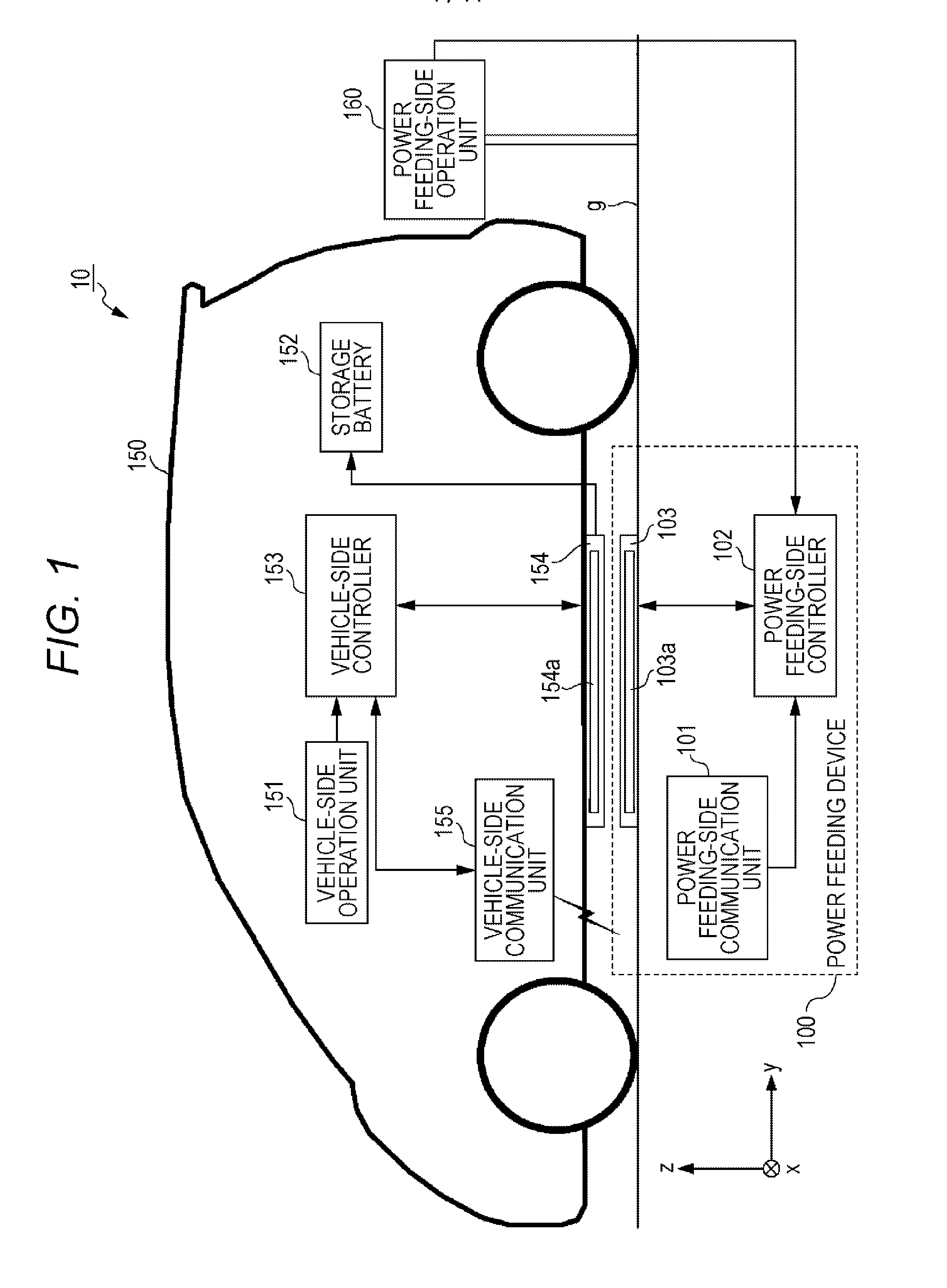
[0022]A configuration of charging system 10 according to a first exemplary embodiment of the present disclosure is described with reference to FIG. 1.

[0023]Charging system 10 includes power feeding device 100, vehicle 150, and power feeding-side operation unit 160. FIG. 1 shows that power can be fed through power feeding coil 103a and power receiving coil 154a opposite to each other.

[0024]Power feeding device 100 is installed on or partially buried in the ground so that power feeding unit 103 is exposed from the earth's surface g. Power feeding device 100 is provided, for example, in a parking space and feeds power to power receiving unit 154 while being opposed to power receiving unit 154 during parking of vehicle 150. Here, power feeding refers to supplying power from power feeding coil 103a to power receiving coil 154a. A configuration of power feeding device 100 will be described below.

[0025]Vehicle 150 is a motor vehicle that runs by the power of storage battery 152, for exampl...

second exemplary embodiment

[0063]While the solenoid coils are used for the power feeding coil and the power receiving coil in the first exemplary embodiment, spiral coils are used for the power feeding coil and the power receiving coil in a second exemplary embodiment of the present disclosure, which will be described below. Note that since a charging system according to the second exemplary embodiment of the present disclosure is configured similarly to that shown in FIGS. 1 and 2 of the first exemplary embodiment, different functions will be described, referring to FIGS. 1 and 2 if necessary.

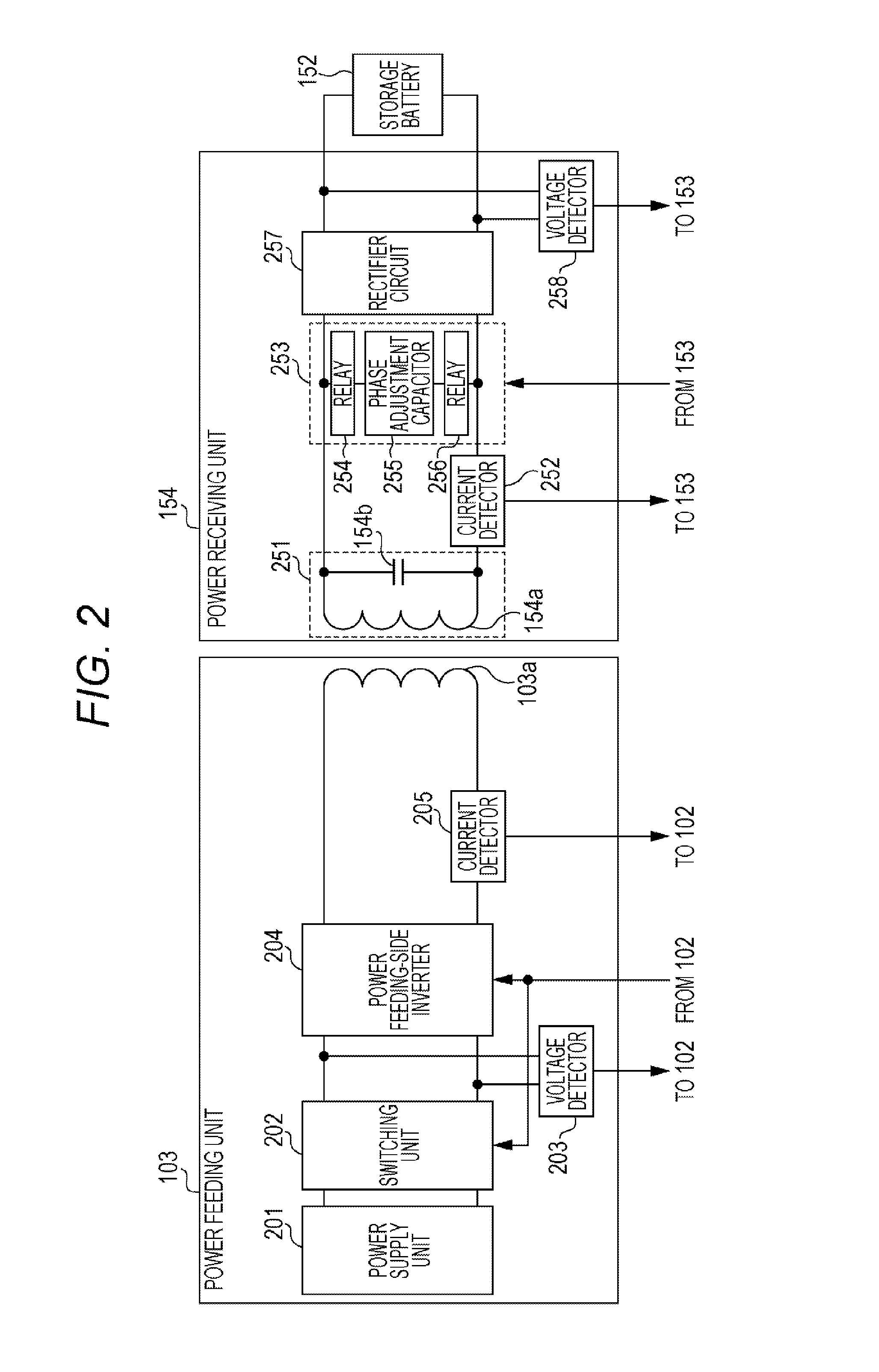
[0064]Power feeding unit 103 has power feeding coil 103a, which can be a spiral coil. Power feeding unit 103 feeds power to power receiving coil 154a through power feeding coil 103a under control of power feeding-side controller 102.

[0065]Power receiving unit 154 has power receiving coil 154a. Power receiving coil 154a can be, for example, a spiral coil and receives power fed from power feeding coil 103a of power feedin...


PUM

PropertyMeasurementUnit
frequencyaaaaaaaaaa
specific frequencyaaaaaaaaaa
phaseaaaaaaaaaa

Abstract

A wireless power receiving device for receiving power wirelessly is configured to include a resonant circuit including a power receiving coil and a resonant capacitor for receiving power from a power feeding coil; and a phase adjustment circuit that is provided at a rear stage of the resonant circuit and adjusts a phase difference between a power feeding coil current and a power receiving coil current at a specific frequency to cancel horizontal magnetic flux.

Description

TECHNICAL FIELD[0001]The present disclosure relates to a wireless power receiving device for wirelessly receiving power fed from a power feeding device on the ground using electromagnetic force.BACKGROUND ART[0002]In recent years, electrically driven motor vehicles (hereinafter simply referred to as a “vehicle”), such as an EV (Electric Vehicle) or a PHEV (Plug-in Hybrid Electric Vehicle), are becoming popular. Such a vehicle, which is equipped with a large-capacity storage battery, stores electrical energy supplied externally in the storage battery and travels using the stored electrical energy.[0003]A method for externally charging a storage battery of a vehicle is known that wirelessly feeds power between a primary coil of a power feeding device on the ground and a secondary coil of a power receiving device on the vehicle using electromagnetic force. Considering power supply from the primary coil on the ground to the secondary coil mounted on the bottom of the vehicle in a wirele...

Claims


Application Information

Patent Timeline
Patent Type & Authority Applications(United States)
IPC IPC(8): H02J5/00H02J50/90H02J7/02H01F38/14
CPCH02J5/005H02J50/90H02J7/025H01F38/14Y02T10/7072Y02T90/14H02J50/12B60L53/122B60L53/126H02J2310/48Y02T10/70H02J7/0049H02J50/80H02J50/70H02J50/005Y02T90/12
Inventor KOIZUMI, MASAYOSHIOHASHI, OSAMUSADAKATA, HIDEKIFUJITA, ATSUSHIOMORI, YOSHIHARU
Owner PANASONIC INTELLECTUAL PROPERTY MANAGEMENT CO LTD
Why Eureka
Try Eureka