Fuel injection device

a fuel injection device and fuel injection technology, applied in the direction of fuel injection pumps, machines/engines, electric control, etc., can solve the problems of power deficiency, black smoke and other problems, increased cost cannot be avoided, etc., to reduce unnecessary radiation, simplify the configuration of electrical circuitry, and high speed

Inactive Publication Date: 2005-06-28
DIESEL KIKI CO LTD
View PDF11 Cites 32 Cited by
  • Summary
  • Abstract
  • Description
  • Claims
  • Application Information

AI Technical Summary

Benefits of technology

[0013]The printed circuit board can be configured to have at least four layers and to also constitute the wiring of the ground side of the high-voltage section using an inner layer of the printed circuit board. The wiring of the ground side can be made solid wiring to reduce unnecessary radiation.
[0014]The fuel injection system according to the present invention is equipped with a booster for boosting the pressure of high-pressure fuel from a common rail so as to enable supply of pressure-boosted high-pressure fuel in addition to high-pressure fuel, and an electric actuator conducts switching to select one or the other of the high-pressure fuel and the pressure-boosted high-pressure fuel as the fuel supplied to the fuel injection valve. If a piezoelectric actuator is used, the switching can be conducted at very high speed. Moreover, unlike the conventional practice of controlling the driving of two solenoid valves to maintain required cycles, fuel pressure switching can be conducted instantaneously in switching valve fashion by a single electric actuator. This eliminates the need to take actuator characteristic variance and temperature characteristics into consideration, simplifies the configuration of the electrical circuitry for drive control, and enables a cost reduction.
[0015]Further, since a multilayer printed circuit board is used to fabricate the control circuit for the electric actuator (e.g., a piezoelectric actuator) so that the wiring of the high-voltage side of the high-voltage section is constituted using an inner layer, insulation breakdown is unlikely even if the voltage of a high-voltage power supply is applied to the electric actuator under high switching speed because the inner layer is coated with an insulating material and therefore has a high withstand voltage. This makes it possible to reduce size by implementing high-density wiring, so that a high packing density can be realized despite the use of a high voltage. While the driving voltage must be set high to realize high speed, this need can be met owing to the excellent insulation performance, so that high-speed driving by application of a high voltage becomes possible to thereby realize fuel injection that is both accurate and fast.
[0016]In addition, effective suppression of noise signal occurrence is enabled by using an inner layer to form the wiring of the ground circuits as solid wiring and thereby minimize the level of unnecessary radiation from the printed circuit board

Problems solved by technology

Power deficiency, black smoke and other problems therefore arise if the high-pressure fuel in the common rail is merely supplied to the fuel injection valves as it is over the whole operating range.
However, since the disclosed system is structured to selectively supply the fuel injection valves with high-pressure fuel from the common rail or pressure-boosted high-pressure fuel from the booster piston by switching control using two solenoid valves, increased cost cannot be avoided because two sets of solenoid valves and associated drive circuits are required.
In view of the scatter in solenoid valve response characteristics and variation in solenoid valve characteristics with temperature change, however, the required switching characteristic is difficult to achieve over the whole range of use temperatures.
Use of a complex and expensive control circuit is therefore unavoidable, so that a problem of high cost also arises from this aspect.

Method used


Image

  • Fuel injection device
  • Fuel injection device
  • Fuel injection device

Examples


Embodiment Construction

[0020]A preferred embodiment of the present invention will now be explained in detail with reference to the drawings.

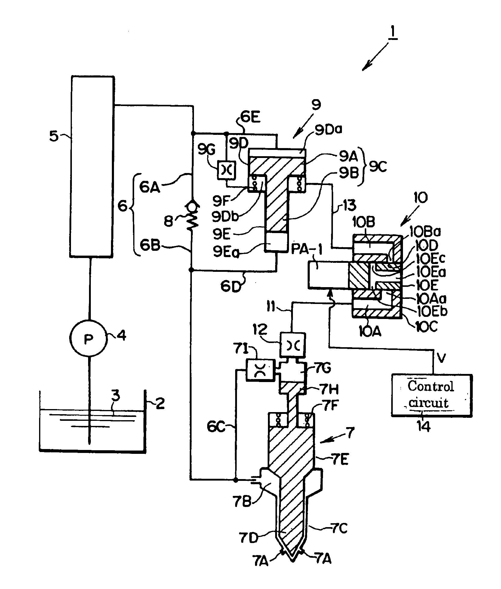
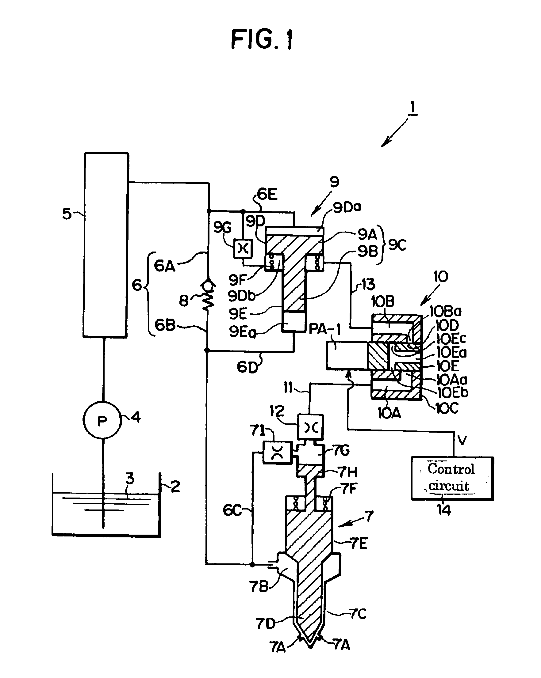
[0021]FIG. 1 is a configuration diagram showing an embodiment of the fuel injection system according to the present invention. The fuel injection system 1 is a common rail type fuel injection system for injecting fuel in an internal combustion engine (not shown) used to drive a vehicle. It is configured to pressurize fuel 3 from a fuel tank 2 with a high-pressure pump 4, accumulate the pressurized fuel in a common rail 5, and supply the high-pressure fuel accumulated in the common rail 5 through a supplied fuel line 6 composed of fuel lines 6A, 6B to a fuel injection valve 7 explained later.

[0022]The fuel injection valve 7 is installed in one cylinder among multiple cylinders of the unshown internal combustion engine. The injection valve 7 directly injects high-pressure fuel into the cylinder. Although FIG. 1 shows only one injection valve 7, a number of injection val...


PUM


Abstract

A check valve (8) and a booster (9) are inserted in parallel in a supplied fuel line (6) connecting a common rail (5) and an injection valve (7), a piston (10E) of a hydraulic circuit (10) is driven for positioning by a piezoelectric actuator (PA-1), the pressures in a chamber (9Db) of the booster (9) and the pressure in a fuel chamber (7G) of the injection valve (7) are selectively lowered by controlling the alignment state between ports (10Eb), (10Ec) provided in the piston (10E) to communicate with a low-pressure portion and an opening 10Aa of a first chamber 10A and an opening (10Ba) of a second chamber (10B) of cylinder (10C), whereby the pressure of the fuel supplied to the fuel reservoir (7B) of the injection valve (7) is rapidly switched to one or the other of high-pressure fuel from the common rail (5) and pressure-boosted high-pressure fuel from the booster (9).

Description

TECHNICAL FIELD[0001]The present invention relates to a fuel injection system configured to inject high-pressure fuel accumulated in a common rail into the cylinders of an internal combustion engine using fuel injection valves.BACKGROUND ART[0002]Recent years have seen wide adoption of common rail type fuel injection systems that are equipped with a common rail for accumulating high-pressure fuel supplied under pressure from a high-pressure pump and are constructed to inject the high-pressure fuel in the common rail into the cylinders of an internal combustion engine through corresponding fuel injection valves at electronically controlled injection timing. For realizing good operating characteristics in this type of fuel injection system, it is preferable, for example, to set the common rail pressure relatively low during idling so as to reduce noise and achieve smooth rotation and to set the common rail pressure somewhat high during low-load operation so as to prevent degradation o...

Claims


Application Information

Patent Timeline
Patent Type & Authority Patents(United States)
IPC IPC(8): F02M59/00F02M59/46F02M59/10F02M47/02F02D41/20F02M63/00F02D41/38F02M47/00F02M51/00F02M55/02F02M61/20H01L41/09
CPCF02M63/0049F02M59/105F02M63/0026F02M47/027F02D41/2096F02D41/3809F02M47/00
Inventor OSHIZAWA, HIDEKAZUTAKEKAWA, YORIYUKI
Owner DIESEL KIKI CO LTD
Why Eureka
Try Eureka