Display device

a technology of a display device and a metal housing, which is applied in the direction of television systems, earth/grounding circuits, pulse automatic control, etc., can solve the problems of limiting the size of the metal housing in the length, width, depth, etc., and reducing the number of grounding sites. , the effect of increasing the complexity of the configuration

Active Publication Date: 2018-03-08
FUNAI ELECTRIC CO LTD
View PDF1 Cites 0 Cited by
  • Summary
  • Abstract
  • Description
  • Claims
  • Application Information

AI Technical Summary

Benefits of technology

[0008]Also, with the technique in the above-mentioned Patent Literature 2 and the technique in the above-mentioned Patent Literature 3, since grounding posts are disposed as evenly as possible along the end or in the interior of the housing, the large number of grounding posts is a drawback in that the configuration is more complicated and the cost is higher.
[0009]One object of the present disclosure is to reduce the number of grounding sites while being able to achieve low impedance everywhere on a housing, and effectively reduce unnecessary radiation, even if the length, width, and other such dimensions of the housing are greater than the half wavelength of the highest oscillation frequency of the oscillator (λ / 2), in a tuner device of a display device in which a housing that houses an oscillator in its interior is disposed on a substrate.
[0010]To achieve the stated object, with the present disclosure, since unnecessary radiation naturally occurs at places of high impedance on the housing, using the grounded sites of the housing as the reference impedance, unnecessary radiation is reduced by providing grounding sites that forcibly lower the impedance at these housing sites where the impedance is high.

Problems solved by technology

However, although the tuner ICs installed in tuner devices today have become smaller and more integrated, there is a limit to how small the capacitors and inductors housed in a metal housing can be made, so there is also a limit to the size of the metal housing in the length, width, depth, diagonal, and other such dimensions.
Accordingly, even though the technique in the above-mentioned Patent Literature 1 is to set the length, width, depth, and diagonal dimensions of the metal housing to be no more than half the wavelength of the signal with the highest oscillation frequency (λ / 2), in actual practice this is quite difficult, and as a result, a range or site occurs in which the impedance is high in the metal housing, and a large amount of unnecessary radiation is produced from this range or site.
Also, with the technique in the above-mentioned Patent Literature 2 and the technique in the above-mentioned Patent Literature 3, since grounding posts are disposed as evenly as possible along the end or in the interior of the housing, the large number of grounding posts is a drawback in that the configuration is more complicated and the cost is higher.

Method used


Image

  • Display device
  • Display device
  • Display device

Examples


first embodiment

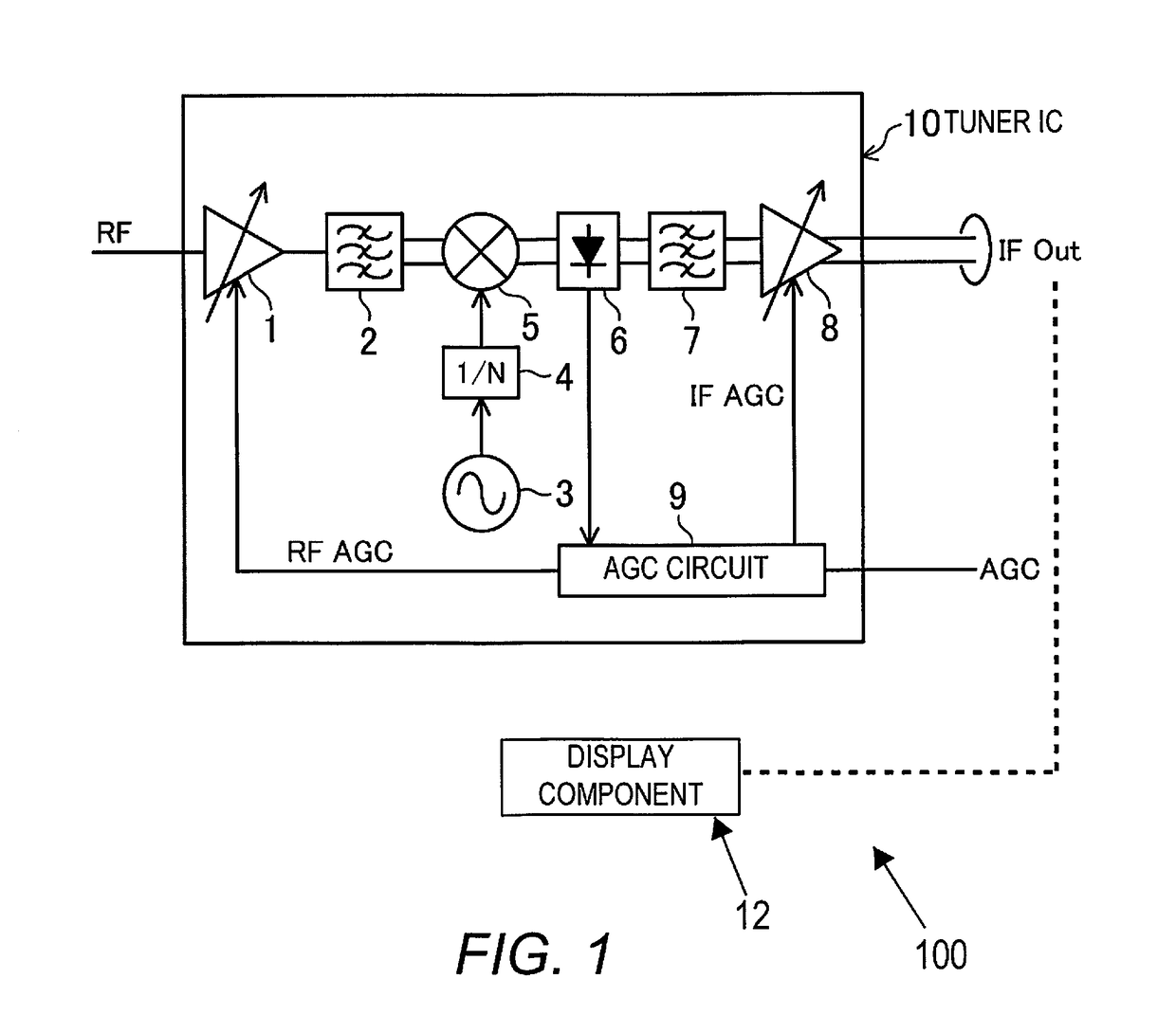
[0060]FIG. 1 is a circuit diagram of a tuner IC provided to a tuner device of a display device 100 pertaining to a first embodiment of the present disclosure. This tuner IC (tuner component) is used for television broadcasts, for example, and its output broadcast signal is outputted to a display component (display) 12, and video corresponding to the broadcast signal is displayed on this display component 12.

[0061]In the tuner IC10 in FIG. 1, 1 is an RF amplifier (gain control amplifier), 2 is an interstage filter, 3 is a VCO / PLL circuit, 4 is a 1 / N circuit, 5 is a mixer, 6 is a detector, 7 is an interstage filter, 8 is an IF amplifier (gain control amplifier), and 9 is an AGC (auto gain control) circuit.

[0062]The RF amplifier 1 amplifies a received signal having an RF frequency of 90 to 767 MHz, which is the frequency of ground wave television broadcasts in Japan, for example, and the interstage filter 2 limits the band of the amplified signal. The VCO / PLL circuit (oscillator) 3 cha...

first modification example

[0106]FIG. 15 shows a first modification example of the second grounding site shown in FIG. 11.

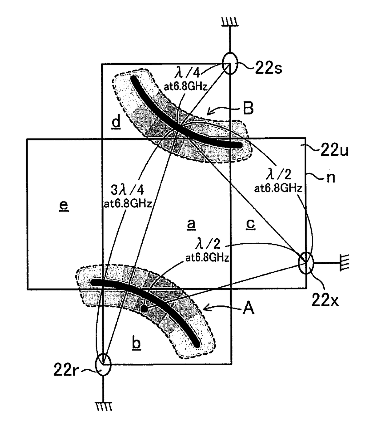
[0107]In FIG. 11, because the two first grounding sites 22r and 22s are located in point symmetry in a developed view of the housing 22, in this modification example, in FIG. 15, the second grounding site 22w in FIG. 11 is replaced by a second grounding site (second site) 22x that is disposed in point symmetry to the second grounding site 22w, that is, on the bottom edge n of the right face c in a developed view of the housing 22.

[0108]Therefore, again in this modification example, it is possible to lower the impedance in both of the high impedance ranges A and B caused by the two first grounding sites 22r and 22s, with just a single second grounding site 22x.

second modification example

[0109]FIG. 16 shows a second modification example of the position of the second grounding site shown in FIG. 11.

[0110]In this modification example, the configuration in FIG. 12 showing this embodiment is combined with the configuration in FIG. 15 showing the first modification example. The second grounding site 22w in FIG. 12 and the second grounding site 22x in FIG. 15 are disposed as second grounding sites (second sites) that lower the impedance of the two high impedance ranges A and B.

[0111]When the two second grounding sites 22w and 22x are both provided, it will be possible to lower the impedance of the high impedance ranges A and B over a wider range if, for example, one of the grounding sites (such as 22w) is disposed at a position that is separated by a half wavelength (λ / 2) from near a position at the oscillation frequency of 6.8 GHz within the high impedance ranges A and B, and the other grounding site (such as 22x) is disposed at a position that is separated by a half wav...


PUM


Abstract

A display device includes a signal processor, a display component, a substrate, and a conductive housing. The signal processor includes an oscillator that outputs oscillation signal. The signal processor processes signal whose frequency is higher than a specific threshold. The display component displays video. The substrate has a ground component. The signal processor is disposed on the substrate. The conductive housing is connected to a first site of the ground component and to a second site that is different from the first site. The first site and the second site are disposed at positions where a first area of the housing in which an impedance is higher than a first threshold due to the first site overlap at least part of a second area of the housing in which an impedance is lower than a second threshold due to the second site.

Description

CROSS-REFERENCE TO RELATED APPLICATIONS[0001]This application claims priority to Japanese Patent Application Nos. 2016-171954 filed on Sep. 2, 2016 and 2016-171958 filed on Sep. 2, 2016. The entire disclosures of Japanese Patent Application Nos. 2016-171954 and 2016-171958 are hereby incorporated herein by reference.BACKGROUNDField of the Invention[0002]The present invention relates to a display device comprising a tuner device that receives television broadcasts, etc., and more particularly relates to a technique for reducing unnecessary radiation (EMI: electromagnetic interference) from a metal housing of the tuner device.Background Information[0003]Japanese Laid-Open Patent Application Publication No. 2015-109551 (Patent Literature 1) discloses a conventional tuner in a display device that reduces unnecessary radiation, which employs a configuration in which the length, width, depth, and diagonal (the linear distance between two vertices that are the farthest apart) dimensions of...

Claims


Application Information

Patent Timeline
Patent Type & Authority Applications(United States)
IPC IPC(8): H04N5/50H04N5/655
CPCH04N5/50H03L7/099H04N5/655H05K9/006H05K9/0007H05K9/0054H05K9/0064H04B15/06H04N5/64
Inventor KODAMA, SHINICHI
Owner FUNAI ELECTRIC CO LTD
Why Eureka
Try Eureka